
Making a Bluetooth Numpad. Part 1: Soldering and Parts
29 Oct 2017Preface
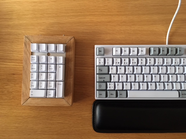
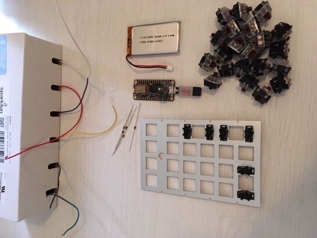
The best way to begin this post is maybe with an after photo. So here it is:
This was a fairly large project, so it made sense to split it into three posts. Each part goes into the different aspects of this project. Electronics, software and woodworking.
Below you’ll find a link to each of the posts:
Hope you find the project interesting!
Part 1
I ended up upgraded my keyboard to a mechanical one a couple months back. A quick and simple purchase, I thought. Oh boy, I went way down the rabbit hole on this one, reading obsessively about the tactile feedback of different switches, of the ergonomic advantages a TKL keyboard can provide, and really, just spent a lot of time looking at pretty keyboards on the subreddit for mechanical keyboards. I even bough a switch tester.
At first I wanted the impossible:
- A TLK keyboard
- ISO layout
- Good build quality. Preferably with a white/grey key and base
- And Bluetooth and usb dual connectivity
There are already few ISO layout keyboards out there, but it was the latter point that made it impossible. At one point I strongly considered creating a keyboard from scratch. But in the end, after weeks of trawling through options, I ended up buying a Varmilo VA88M. No Bluetooth, though.
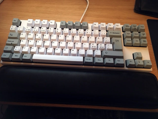
The keyboard is missing a numpad, as you can see, which is ok 90% of the time. But, sometimes you need to input a lot of numbers, and that is when I really miss it. That gave me the idea to create my own Bluetooth numpad. A device you can easily remove from your desk, when not in use. Perfect!
And by the way, this is my first experience with electronics, soldering and so on. The guide might, therefore, be helpful to other novices out there.
Buying the Parts (and the Long Wait)
Since I’ve had no prior experience with electronics, I had to buy a lot of stuff. I’ll create two lists below. The first will list some essentials for electronics work, and the next will list components needed to create the numpad. By the way, buying things off of eBay can be a slow affair, especially when it ships from China.
Essentials
- Soldering iron
- Solder wire
- Solder sucker
- Safety goggles
- Helping hand stand
- pick set
- Wire cutter
- Solder wick (Optional)
- Multimeter (Optional)
Numpad
- Donor numpad. (Satan mechanical keyboard from AliExpress)
- Includes Gateron switches, metal plate and stabilizers which will be used in this project.
- Came assembled, which explains the next step below.
- Hook-up wire. (SparkFun, Solid Core, 22 AWG)
- Adafruit Feather 32u4 Bluefruit LE
- Adafruit Lithium ion polymer battery
- USB Micro B Male to Mini B Female
- 1N4148 Diode
- On/Off switch
- Wood Enclosure
Desolder the Donor Numpad
The plan is to hand wire the keyboard matrix to the Adafruit microcontroller. Unfortunately, the donor numpad came pre assembled, which meant I had to desolder it. This was the first time desoldering, so I was glad I did not need to keep the PCB. Before I began I watched a couple of youtube videos on how to desolder and solder (1, 2). In addition, I read the amazing soldering is easy comic by Mitch Altman, Andie Nordgren, and Jeff Keyzer.
Prepare the Equipment
Heated the soldering iron to around 370 degrees Celcius. Soldering wire is missing from the picture below. Safety goggles was also equipped at this point.
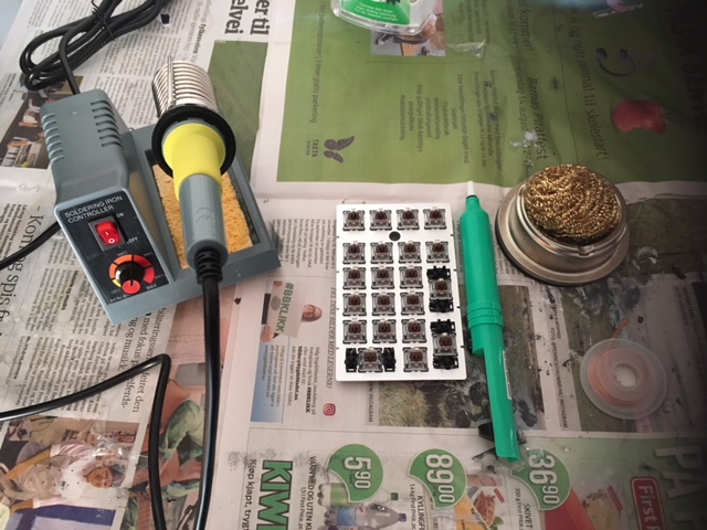
We want to desolder all the switches and LEDs from the PCB, in order to free the metal plate from the PCB. We will later hand wire the switches to the microcontroller.
Each switch had 4 through-hole connection points. 2 for the LED and 2 for the switch. With 21 keys in total you need to do a lot of desoldering.
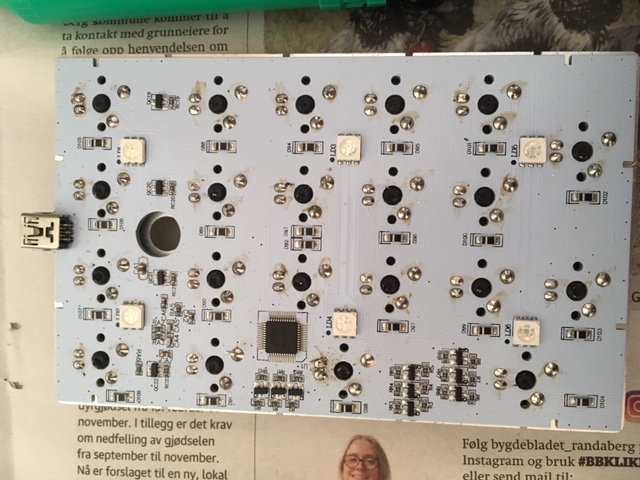
Melt All the Solder!
It will probably take some tries before you get a good technique on how to melt the solder and remove it with the soldering pump before it solidifies. I found that the most effective way was to add a bit of solder to the connection to properly melt to solder. When it melted I would quickly and forcefully put the tip around the hole to form a vacuum before sucking the solder into the pump.
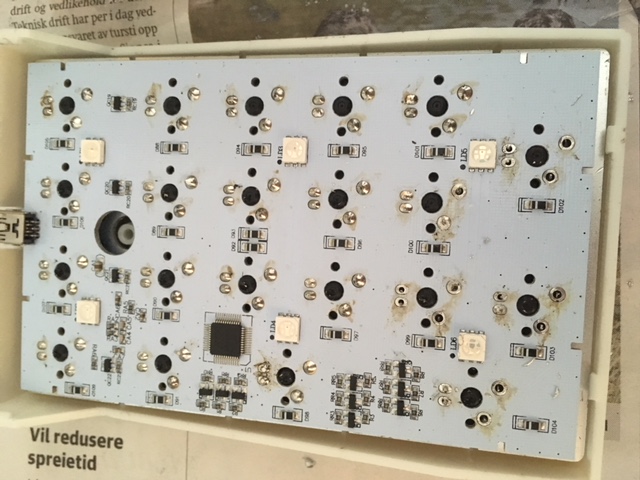
At some connections I failed, by only sucking out some of the solder. Typically caused by not getting a tight seal around the hole with the solder sucker. In those instances, I would add fresh solder to the hole and try again. In addition, to pry loose the switch and LED pins, I lightly wiggled the pins using a metal pick. With the switch pins free, I then applied pressure to pop the switch out.
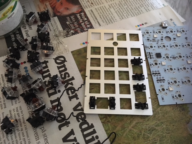
Store Components
Below, you see the finished result. 21 switches, LEDs, and the metal plate. Most of the parts will play a part in the next section, when we hand-wire the switches back onto the metal plate.
The Keyboard Matrix
On a numpad you want to end up with 4 rows of wires connected to all switches, and 6 column connections to all switches through diodes. A good explanation of how a keyboard matrix works can be found here and here. Make sure you somewhat understand the theory before beginning. I’ll show a side by side comparison of the finished circuitry and the keyboard matrix diagram below. I mixed up row and column a bit when testing the numpad in the Arduino IDE, so an image as below would have been useful.

R1 to Rn should each have a pull-up resistor (often integrated in the MCU) which keeps the input at HIGH if switches in that row were not pressed and LOW if any were pressed. Each column is scanned one at the time, when reading which switches have been pressed. This happens very fast so this iterative scanning is not noticeable. For instance, when C2 is scanned, C2 is set to LOW, and input R1 to Rn are read. If switch C2-R1 is pressed, it will close the circuit from R1 to C2 (ground), and make the input R1, LOW. Please read the links to get much better and more detailed picture of how these matrices work!
Hand Wiring the Numpad
While doing this step I followed this guide, closely. You’ll need diodes, wire, the metal plate, stabilizers and switches to do this step.
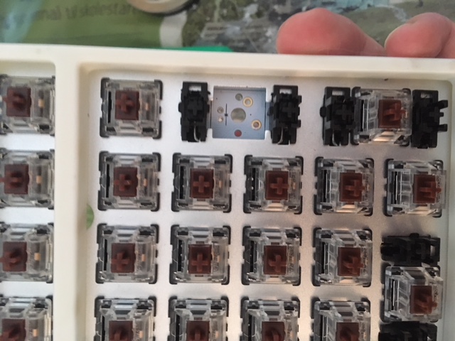
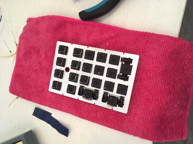
Pop the switches and stabilizers into the numpad plate.
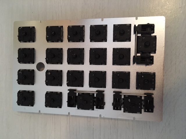
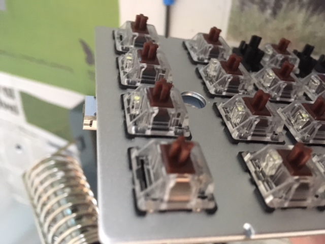
I had to glue some of the switches to the plate, but most fit snugly into the plate. Remember to place all the switches in the same orientation, as you see in the picture below. Though, I believe the switches are bidirectional.
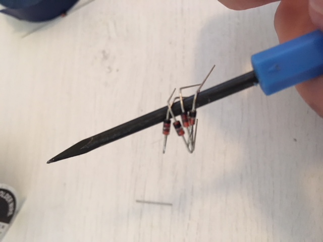
I then bent the diodes into shape. Did it for 5-6 diodes at the time. Bending the diodes using a pick tool was much simpler, and resulted in sharper angles.
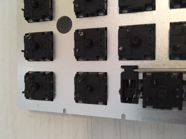
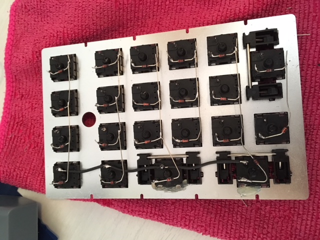
Then you solder the bent diodes to the top most connection of the switches in each column. A soldered column of diodes can be seen below. Note that the black band (cathode) must be placed correctly. It has low resistance to current in one direction but not the other. So do this carefully. You see how the diodes are soldered on below. Below the switch pin with the black band away from the connection.
Another tip when soldering, is to start off by add some solder to all the switch pins. Then, place the diode correctly, touching the pin, and heat up the solder that is already on the pin.
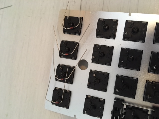
Connect the diodes to the pins, and then solder the diodes together as seen below. After that has been done, it is a good time to use a wire cutter and remove excess wire.
Two and a half columns done!
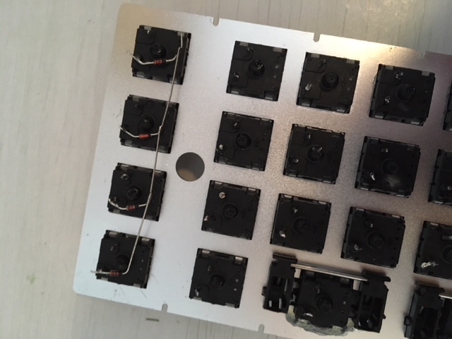
All diodes soldered on. As you see, all the diodes in one column are connected. And the direction of the diodes are correct.
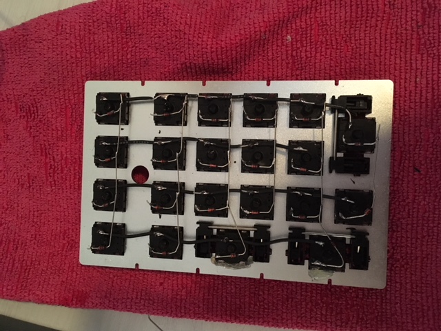
Then you need to prepare the wires that will go to all the switches in each row. I trimmed the ends and used a small knife to trim away the shielding from areas of the wire where the middle pins are located. Try to remove the least amount of rubber shielding, since rows and columns will cross each other, and possibly touch.

First row wire soldered on.
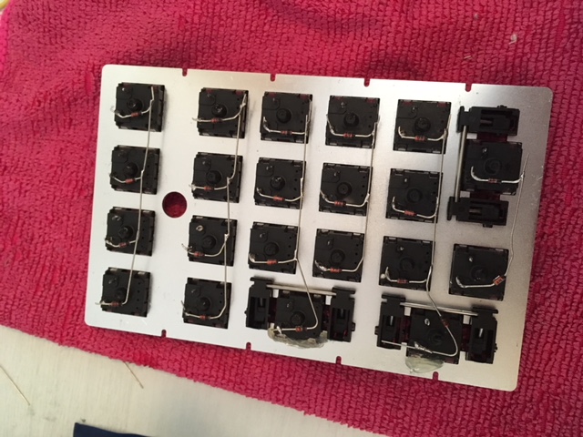
All row wires prepared and soldered onto the numpad.
Connecting the Bluefruit MCU
The matrix itself is complete. The only thing left is to connect the matrix and the microcontroller. The plan is to stack the microcontroller and the battery on top of the matrix. This will, unfortunately, result in a slightly fat numpad.
As you can see below, I was a bit generous with the wire. First I connected the end of each column to a wire.
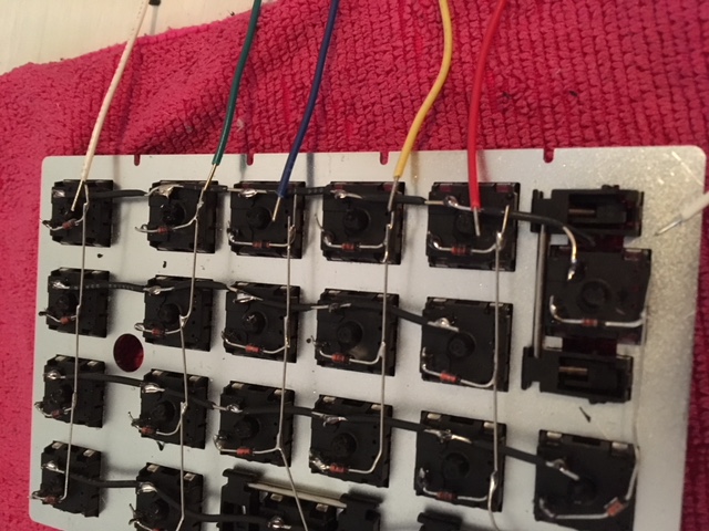
Then I connected the left most switches in the row with wire.
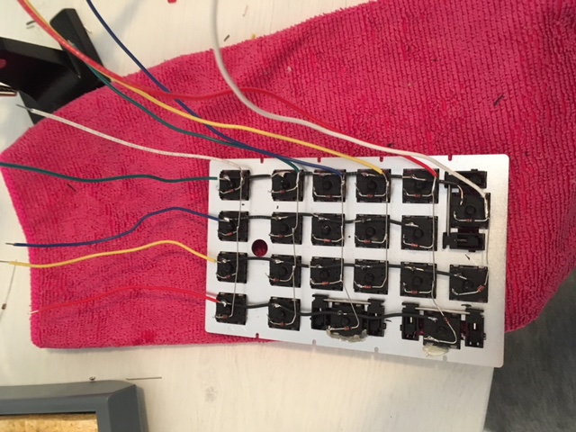
A helping hand stand proved very useful here.
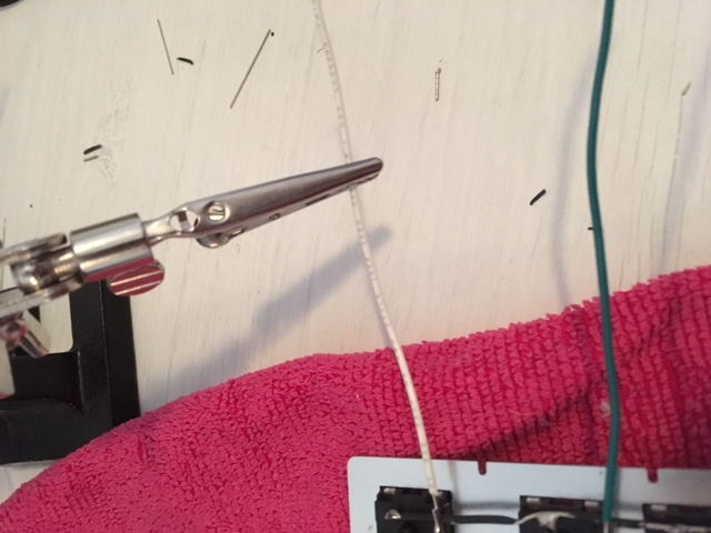
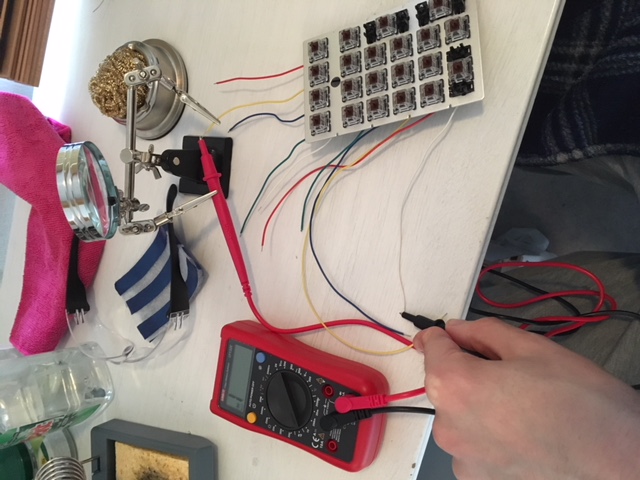
Before soldering wires to the microcontroller, I used a multimeter to test continuity. It show “1” if the circuit is open, and beeps if it is closed. So each key could be tested by probing the correct row and column, and pressing the key down.
I then trimmed each wire down to avoid too much excess wire and soldered them to the microcontroller. The pinouts diagram can be used to decide which pins on the MCU you can use. You’ll need 10 general purpose input/output pins. The wires are a bit stiff so the MCU actually float a small distance above the keyboard matrix.

Finally, time to test the numpad!
Connect it to your computer. You probably need to install some drivers to enable support of Adafruit boards in the Arduino IDE. Setup guide here.
I wrote a simple script that scans the columns and reads which buttons have been pressed. It outputs the position or index of a key rather than the value of the key. Works well for testing that key strokes are registered by microcontroller.
#define ROW_0 22
#define ROW_1 19
#define ROW_2 21
#define ROW_3 20

#define COL_0 13
#define COL_1 12
#define COL_2 11
#define COL_3 10
#define COL_4 9
#define COL_5 6

#define DIGITAL_OFF 0
#define DIGITAL_ON 1

int rows[] = {ROW_0, ROW_1, ROW_2, ROW_3};
int cols[] = {COL_0, COL_1, COL_2, COL_3, COL_4, COL_5};
int current = 0;

void setup() {
  pinMode(ROW_0, INPUT_PULLUP);
  pinMode(ROW_1, INPUT_PULLUP);
  pinMode(ROW_2, INPUT_PULLUP);
  pinMode(ROW_3, INPUT_PULLUP);
  pinMode(COL_0, OUTPUT);
  pinMode(COL_1, OUTPUT);
  pinMode(COL_2, OUTPUT);
  pinMode(COL_3, OUTPUT);
  pinMode(COL_4, OUTPUT);
  pinMode(COL_5, OUTPUT);
  Serial.begin(9600);
}

void setAllToValue(int val) {
  digitalWrite(COL_0, val);
  digitalWrite(COL_1, val);
  digitalWrite(COL_2, val);
  digitalWrite(COL_3, val);
  digitalWrite(COL_4, val);
  digitalWrite(COL_5, vpual);
}

void activateOneRow(int row) {
  setAllToValue(DIGITAL_ON);
  digitalWrite(row, DIGITAL_OFF);
}

void loop() {
  current = (current + 1) % 6;
  activateOneRow(cols[current]);
  for (int i = 0; i < 4; i++) {
    int val = digitalRead(rows[i]);
    if (val == 0) {
      Serial.print(current);
      Serial.print(" ");
      Serial.print(i);
      Serial.print("\n");
    }
  }
  delay(50);
}
So, the numpad basically works. However, it does not act like a keyboard yet, and can’t connect to a computer as a bluetooth device. An attempt at solving that will be done in the next post.
Thank you for reading!