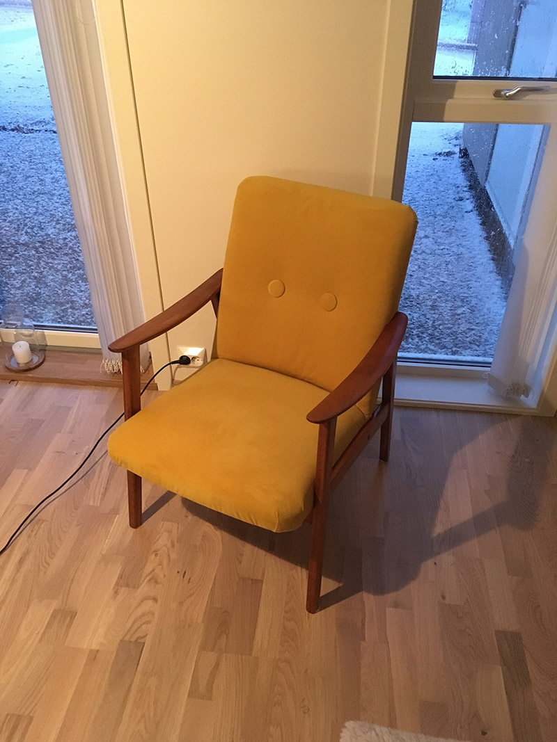
A few months back we moved into a new place. Everything was new and crisp, with white walls and white stained wood flooring. To add some character to the place we decided to decorate with fairly colorful furniture. The first thing we bought for the living room was a blue couch. We then wanted a simple armchair of sorts to complement the couch. Not long after, the chair had to be yellow and have velour chair cushions. And, used furniture are pretty popular nowadays. So yep, a simple retro yellow armchair. How hard can that be to find…
Turns out, pretty hard. Yellow velour fabric on retro armchairs are not that common, actually. The idea of doing some DIY upholstery had been brewing in my mind for some time, and this seemed to be the perfect opportunity.
In all, the project took around a week. Most evenings on work days and the weekend were spent working on the chair.
Materials and Tools
Item
Quantity
Cost
Used armchair
1
$86
Staple gun
1
$11
Staples 8mm
A shit ton
$3
Yellow velour fabric
3 m
$50
Yellow velour buttons
2
$5
Upholstery foam
3 m
$25
Cotton batting
3 m
$15
Upholstery nails
3 m
$3
Denim sewing thread
1
$4
Curved upholstery needle
1
$3
Total
$205
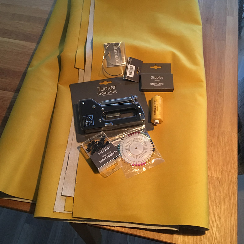
These are the items bought specifically for the project. All materials were bought at Stoff og Stil, a sewing supply store in Norway. In addition to the items listed above, the project required some basic tools. A round nose plier, side-cutting plier, hammer, scissors and a screwdriver. I also used some wood glue and a wood cleaner/wax remover product. The tools all depend on what chair you’re working on, and what you have laying around.
Finding a Suitable Chair
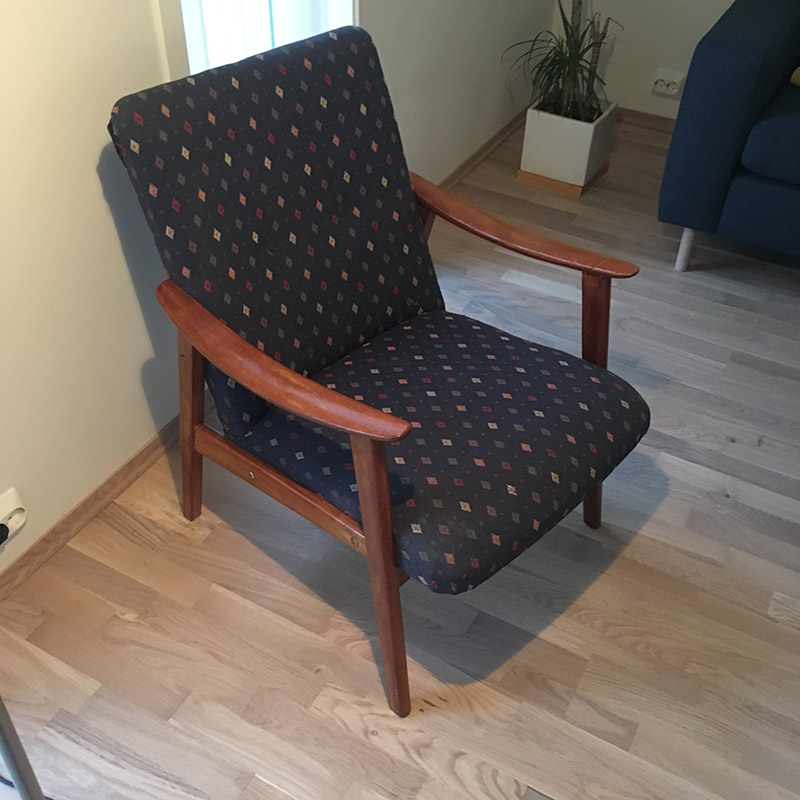
We looked around online and in different used furniture stores. We finally found a chair at NMS Gjenbruk, a local thrift store, for around 700 NOK. Not that cheap, but it looked exactly like what we wanted. A simple Scandinavian style armchair. It did not have any upholstered fabric on the armrests, only the chair pad and back, which is good when you’ve never done anything fabric related before. The chair pad and back is challenge enough. So, go for something simple, if you want to attempt a similar project.
Buying Supplies and Fabric
This step turned out to be hard to do in one go, even though I tried. I had to go back a couple of times for things I suddenly realized that I needed.
Dismantling the Chair
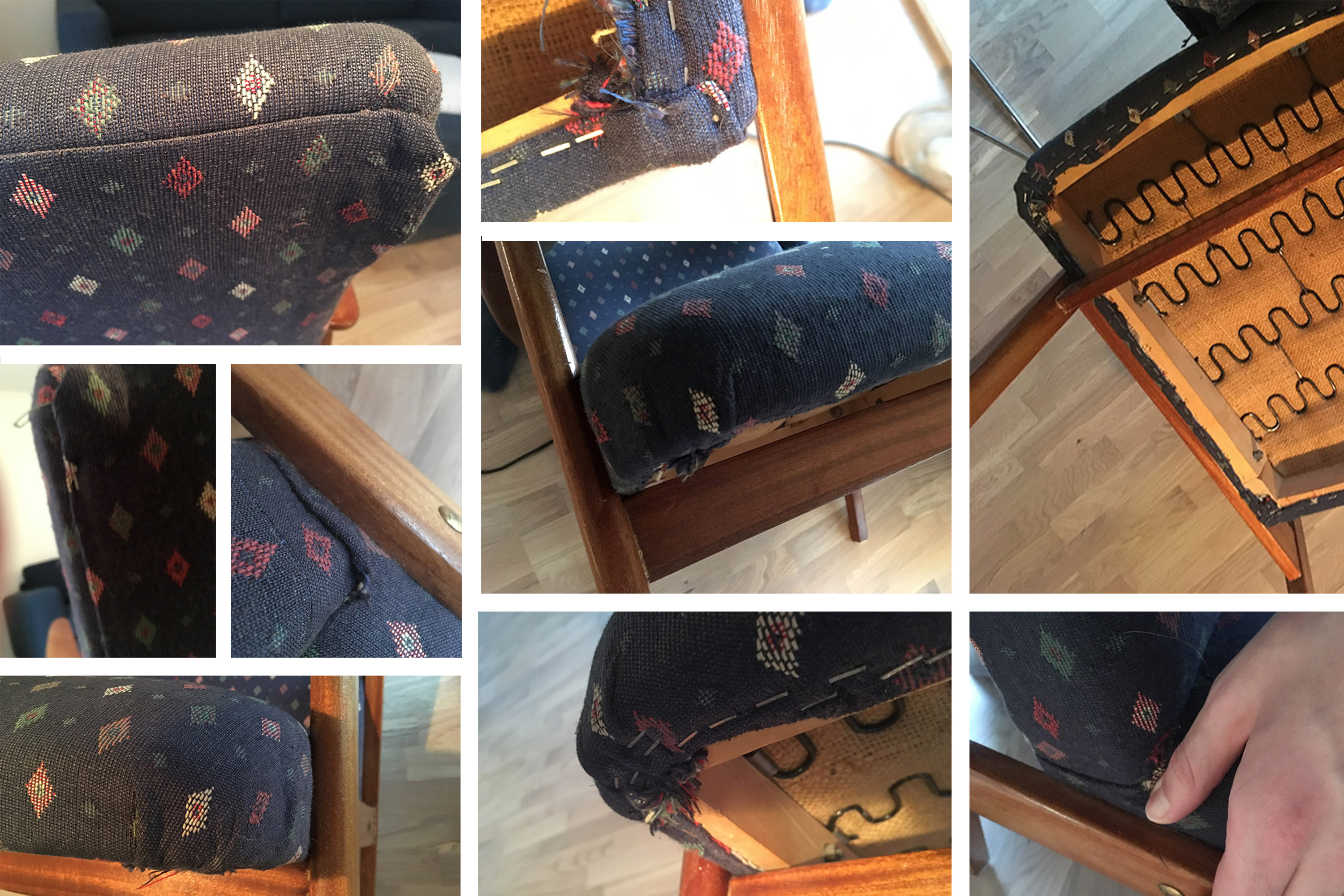
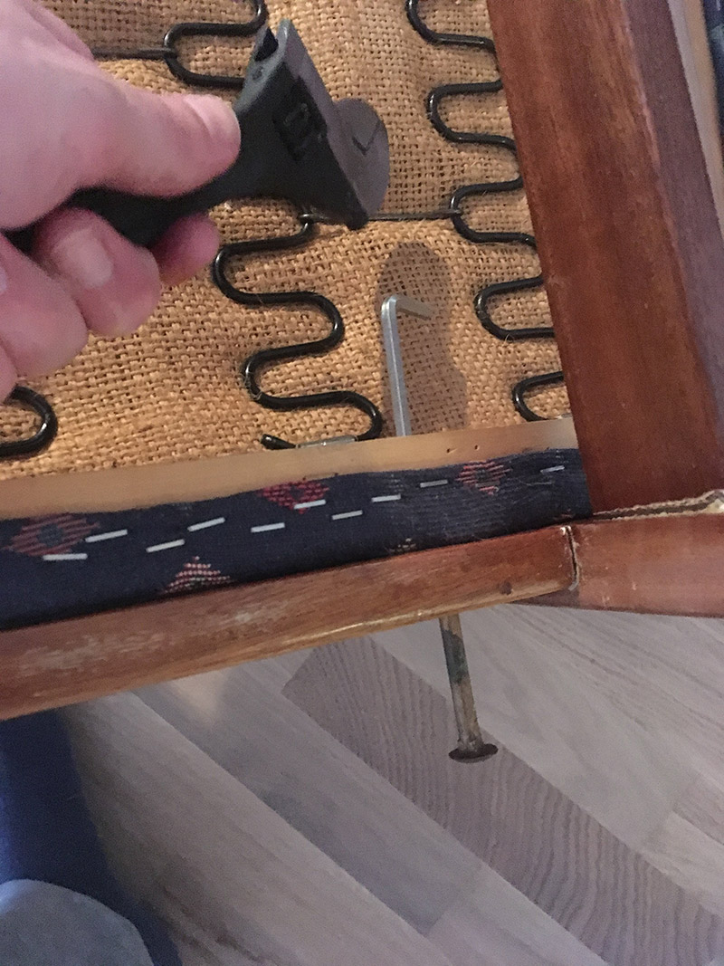
If you plan to do a similar project, remember this: Take a lot of pictures while dismantling the chair. As you can see from the pictures below, be meticulous in recording how the original upholstery work was done, in order for you to replicate it later. It will also serve as a way to determine the order of how the new fabric pieces should be attached. For instance, in my case the chair pad fabric should be attached after the back support fabric.
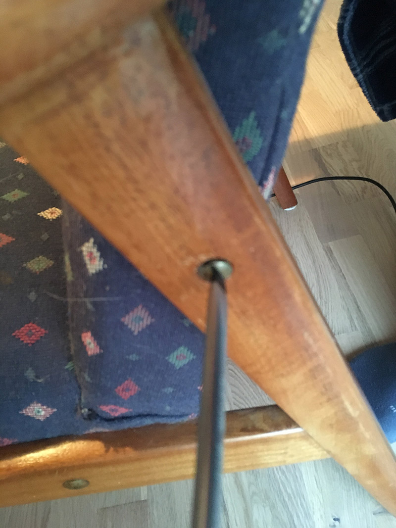
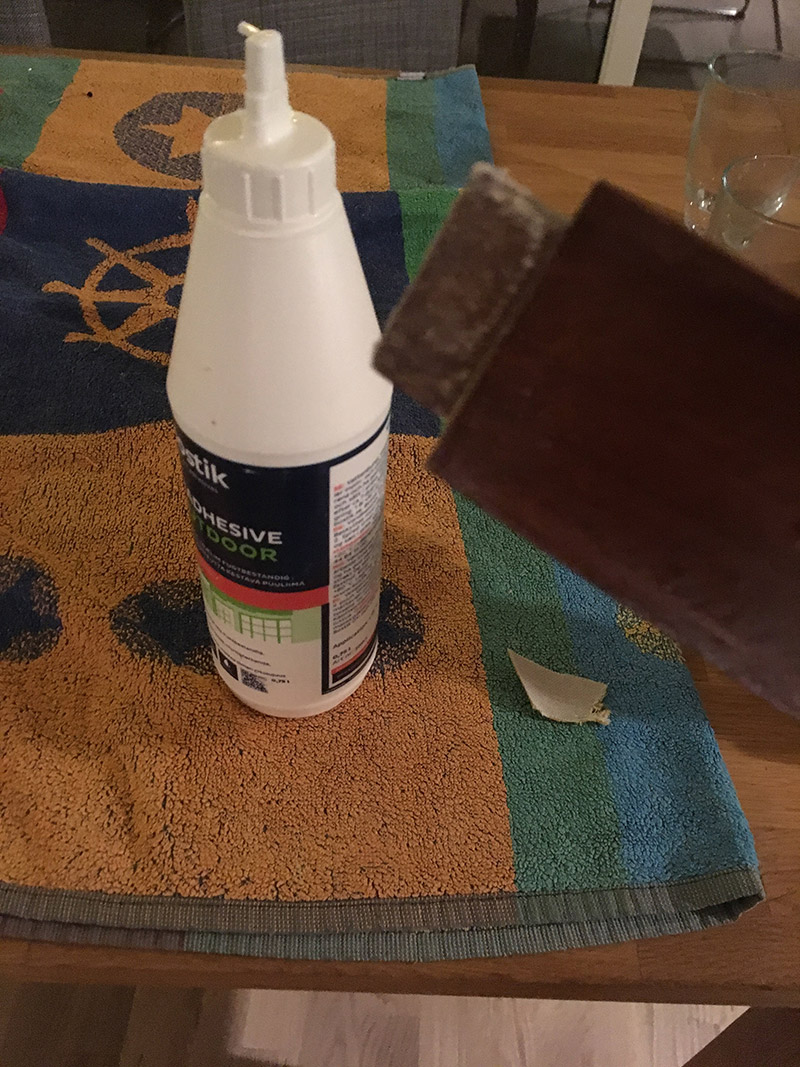
The chair is pretty old, which meant that the bolts holding the chair and the base together were hard to get out. I had to apply some force to a hex key positioned at the tip of the bolt, to get them out. Once out, I cleaned the brass bolts and fasteners in a water salt and vinegar solution. Later, I applied some grease on the bolts and fasteners.
Found this underneath the chair. Product number 2383 and made by P.I Langlo factories. Nothing about what year it was produced, which I am a bit curious about.
Remove the Original Upholstery
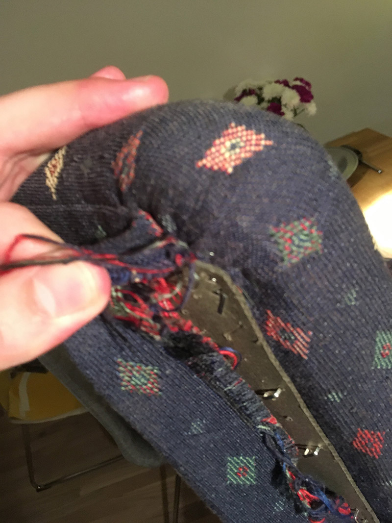
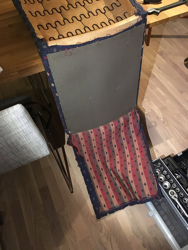
Again, take a lot of pictures! In addition, remove the old fabric without destroying it, because you can use the original fabric as a template when measuring up the new fabric, batting and foam later.
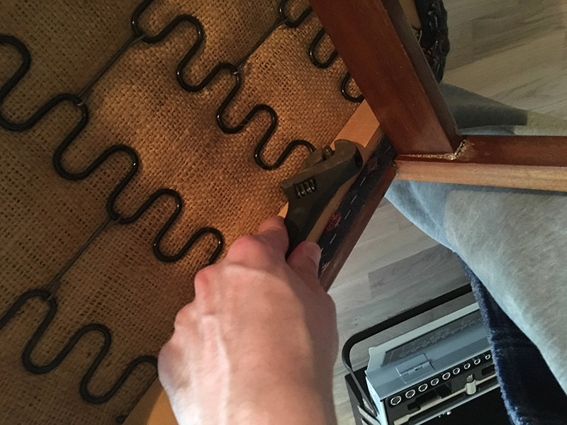
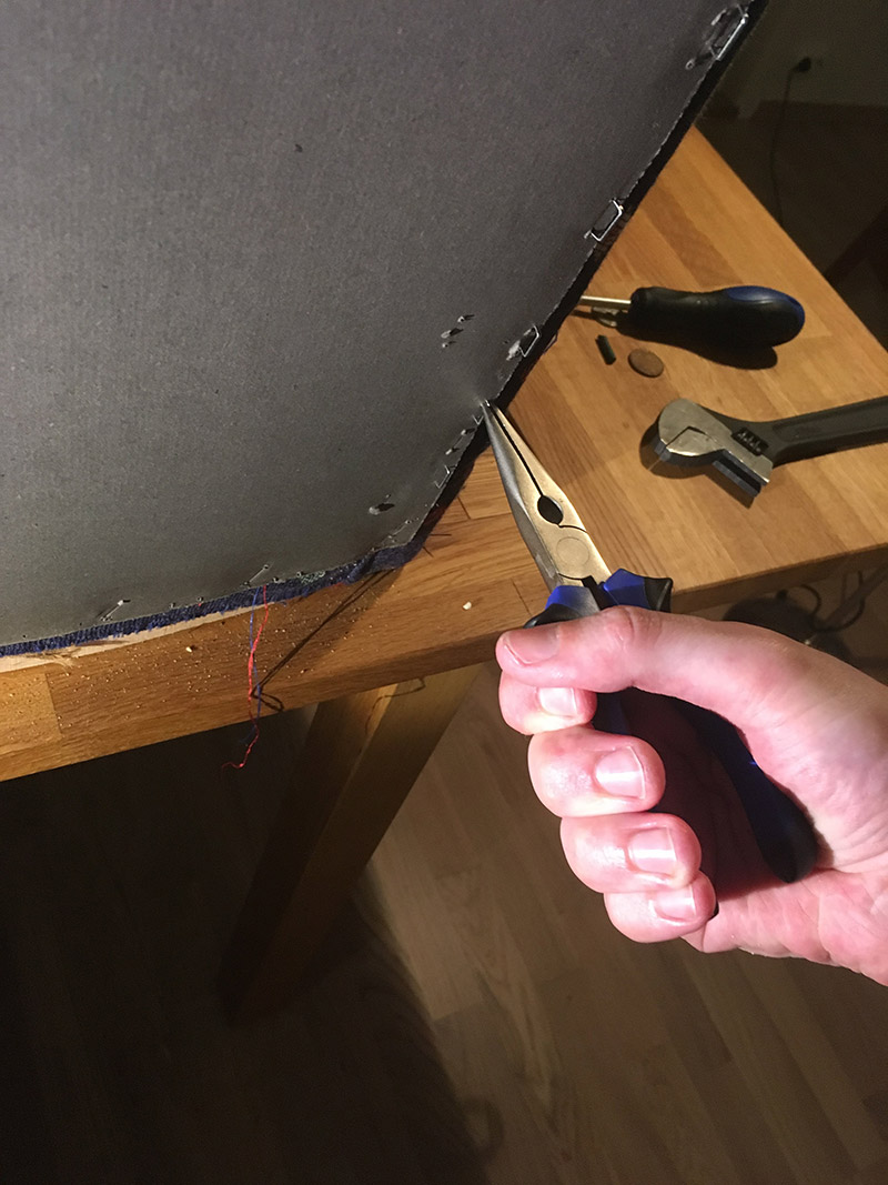
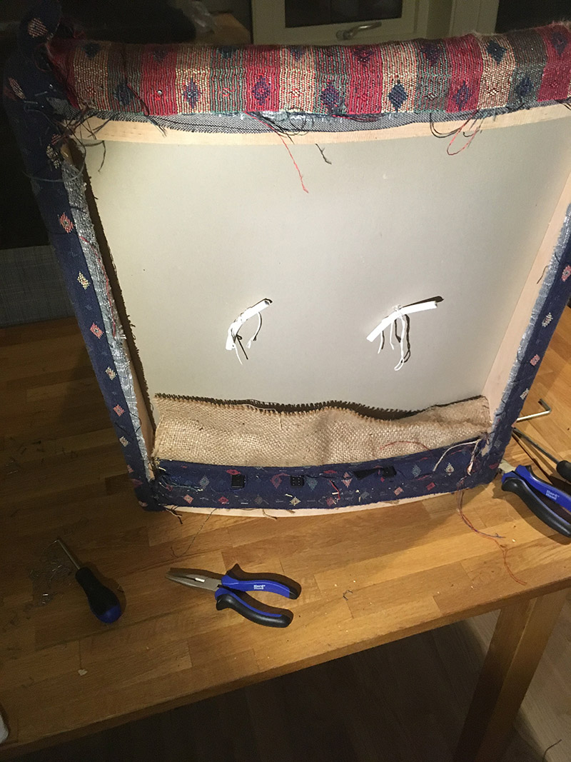
A plate, that had a cardboard feel to it, was found underneath the fabric on the back. I managed to reuse it by carefully removing all the staples that attached it to the wood frame.
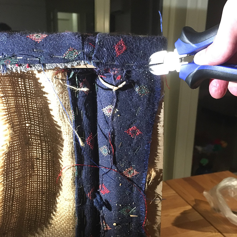
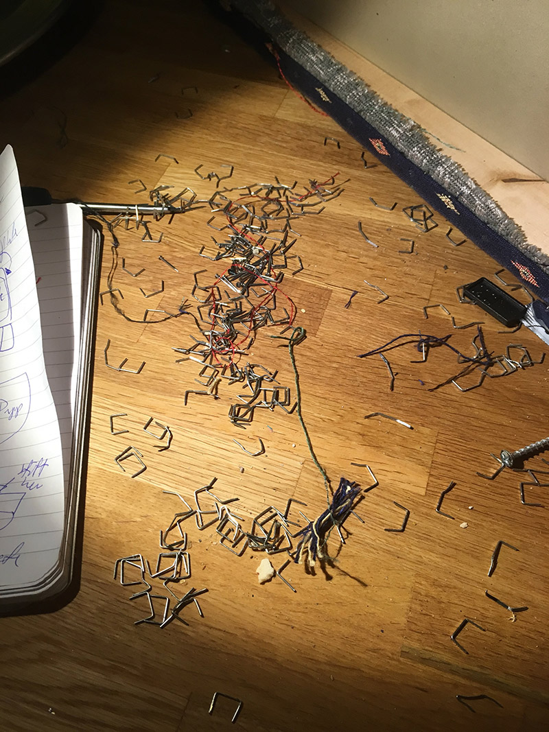
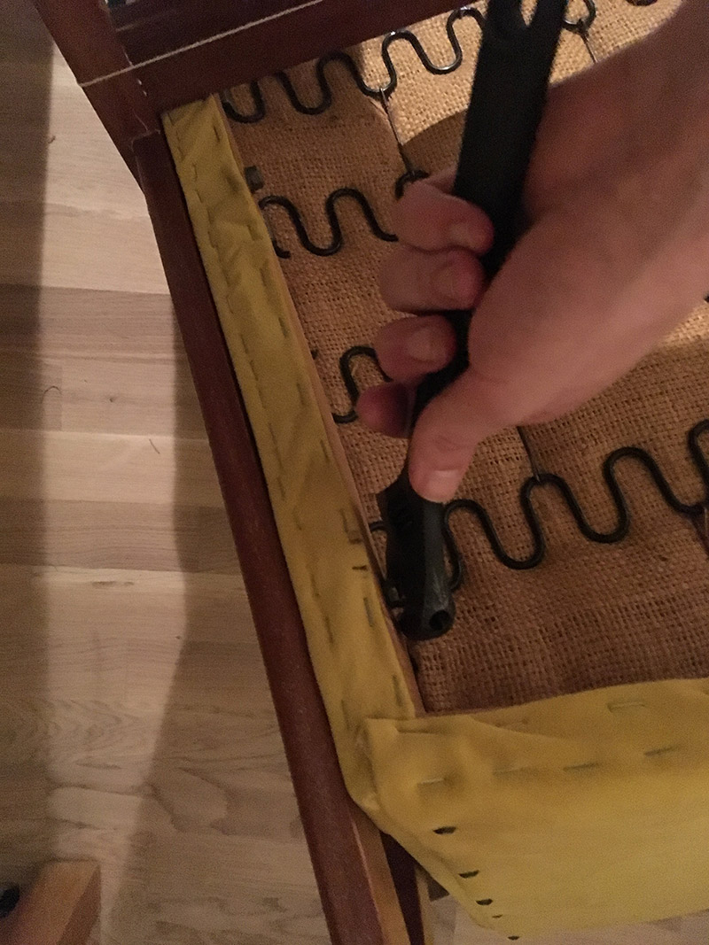
A lot of staples. Some of the staples were quite hard to get out. In order to get them out, I first split the staple in two with side-cutting pliers, and dragged each part out with the round nose plier.
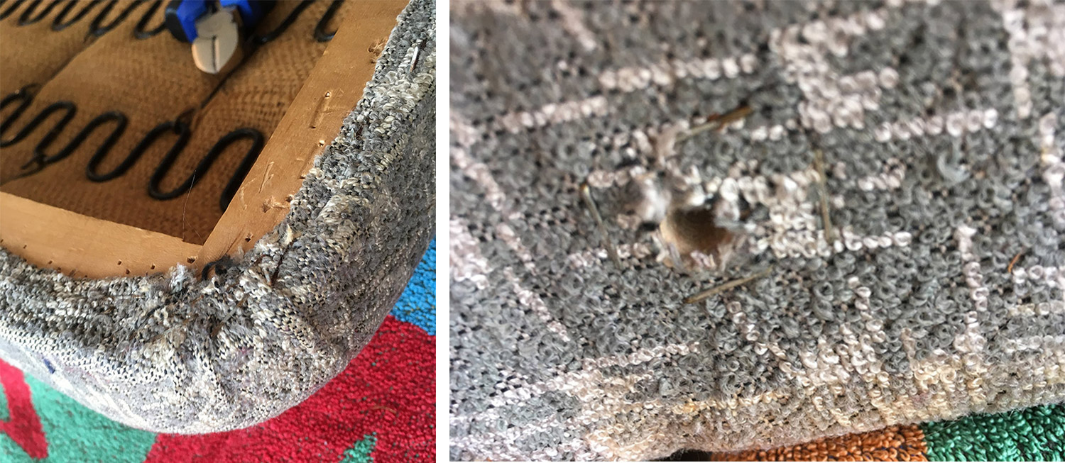
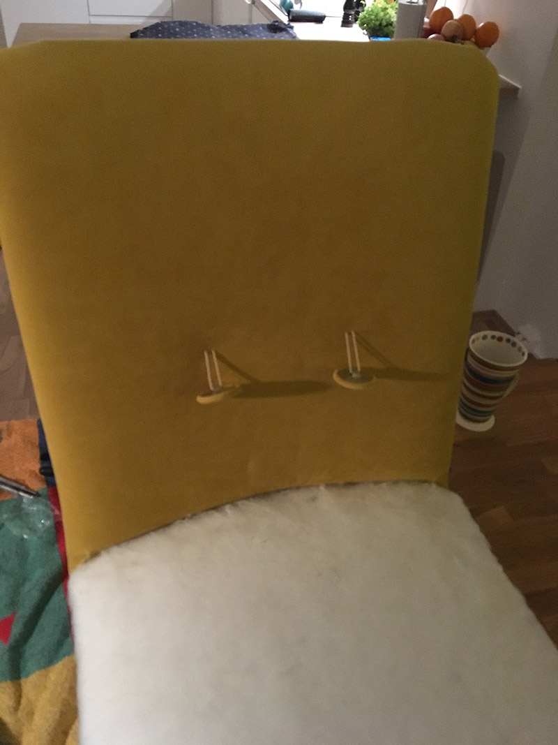
After having removed the cardboard covering, the interior could finally be seen. As you can see from the picture above, the buttons on the back support are secured by string and pieces of electrical wire. Which made me wonder if someone had reupholstered this chair before, maybe.
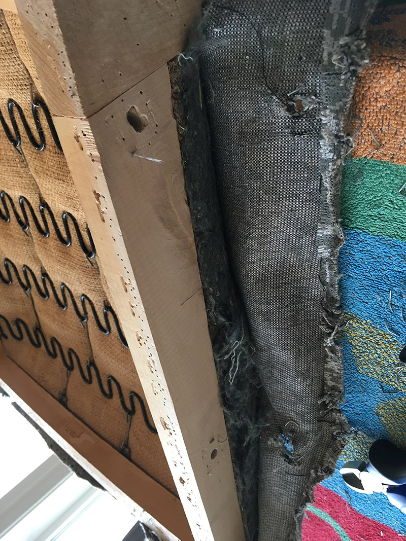
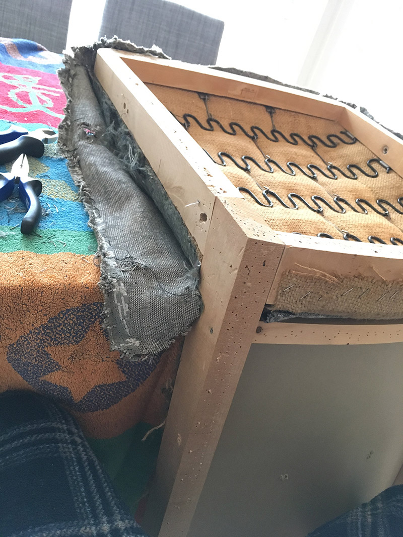
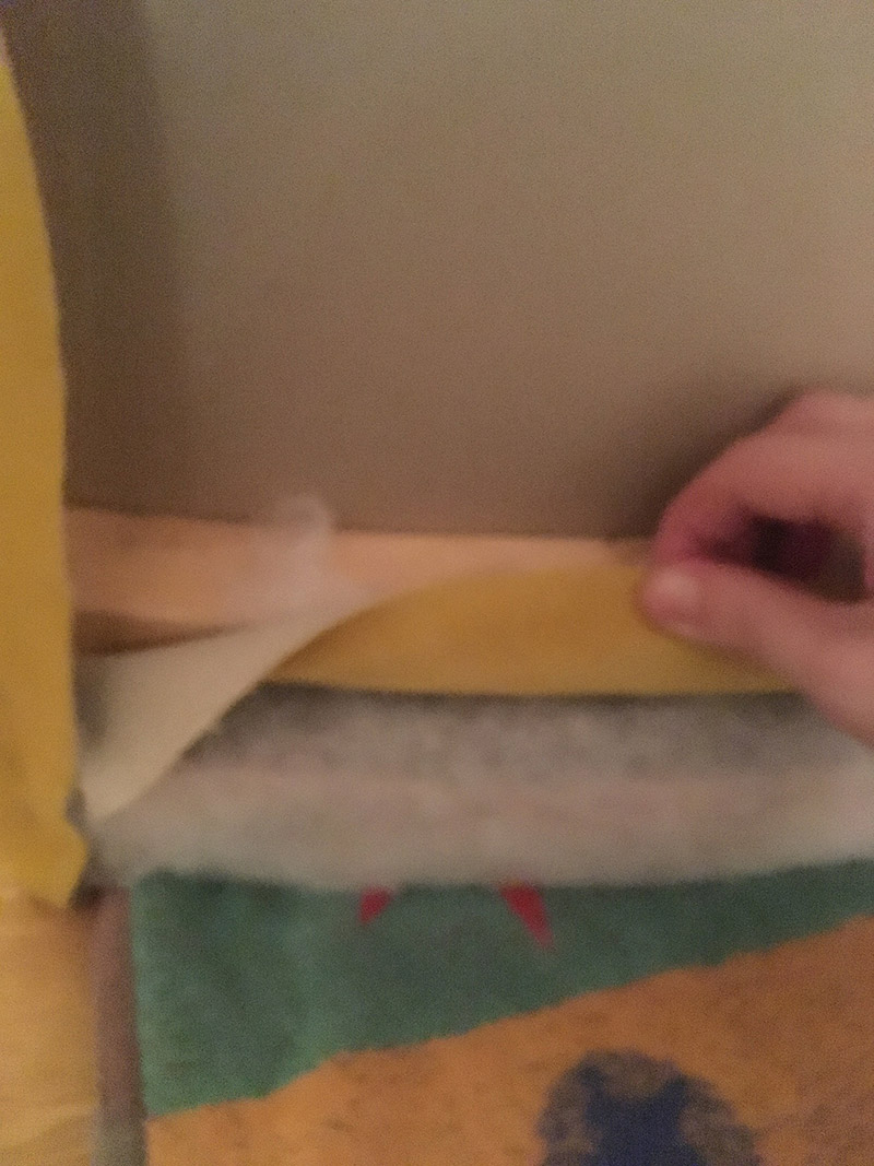
Uh oh! Another layer of fabric, which meant even more staples to pull out. This was also the point where I realized I maybe needed a layer of cotton batting, underneath the yellow velour fabric. This helped me secure the foam cushions, and can give the surface a more even finish.
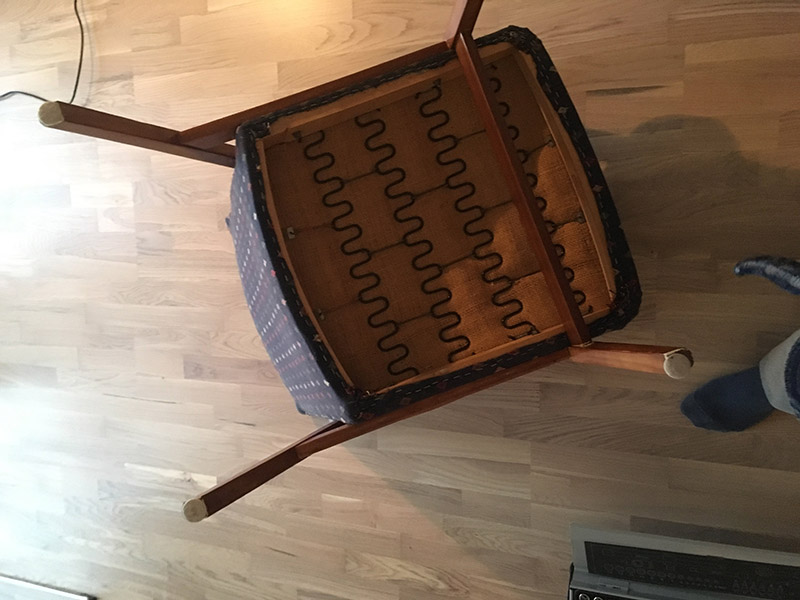
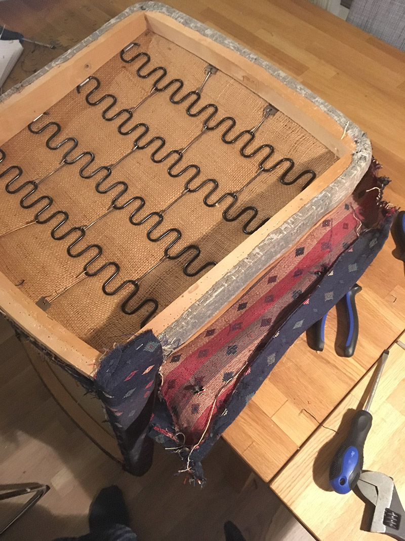
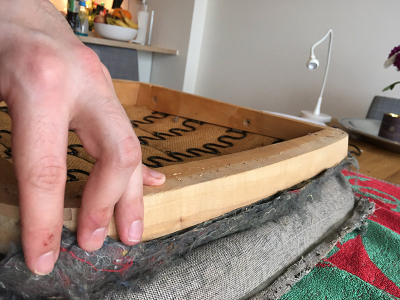
Shows how the fabric from the back support and chair pad is attached to the wood frame.
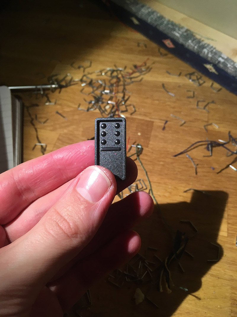
that’s where all the missing domino pieces go! Found it inside the frame of the armchair.
First layer removed. Another layer to go! My hands were getting sore at this point from pulling out so many staples.
At this point I got my first glimpse of what furniture stuffing had been used. Something similar to needled wool felt.
It was much more surprising to find hay beneath the needled wool felt. Apparently, it is common to use straw as a base layer in furniture filling. I had no idea!
In the end I decided to replace the needled wool felt, since it smelled somewhat old. The straw, however, I decided to keep just because it looked very hard to remove. And it didn’t smell all that much, either.
Took a picture at this point to remember to staple around the hole where the bolts go. It seemed important.
Pulling out all those staples left a lot of small holes in the wood frame. I ended up applying some wood glue to fill them up. Not sure if that was necessary, but it sure felt good.
Cutting Foam and Attaching the Cotton Batting
Unfortunately, from this point forward I became a bit carried away, and did not take as many pictures as I should. Hopefully, there are enough to show how the new upholstery was added.
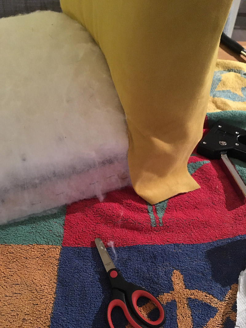
Here, I used the previous furniture filling to get an idea of how to cut the foam. I measured up the foam, drew lines with a sharpie, and did a rough cut of the foam. Afterwards, I put the foam on the chair and made some finer adjustments to it, as you can see in the picture above.
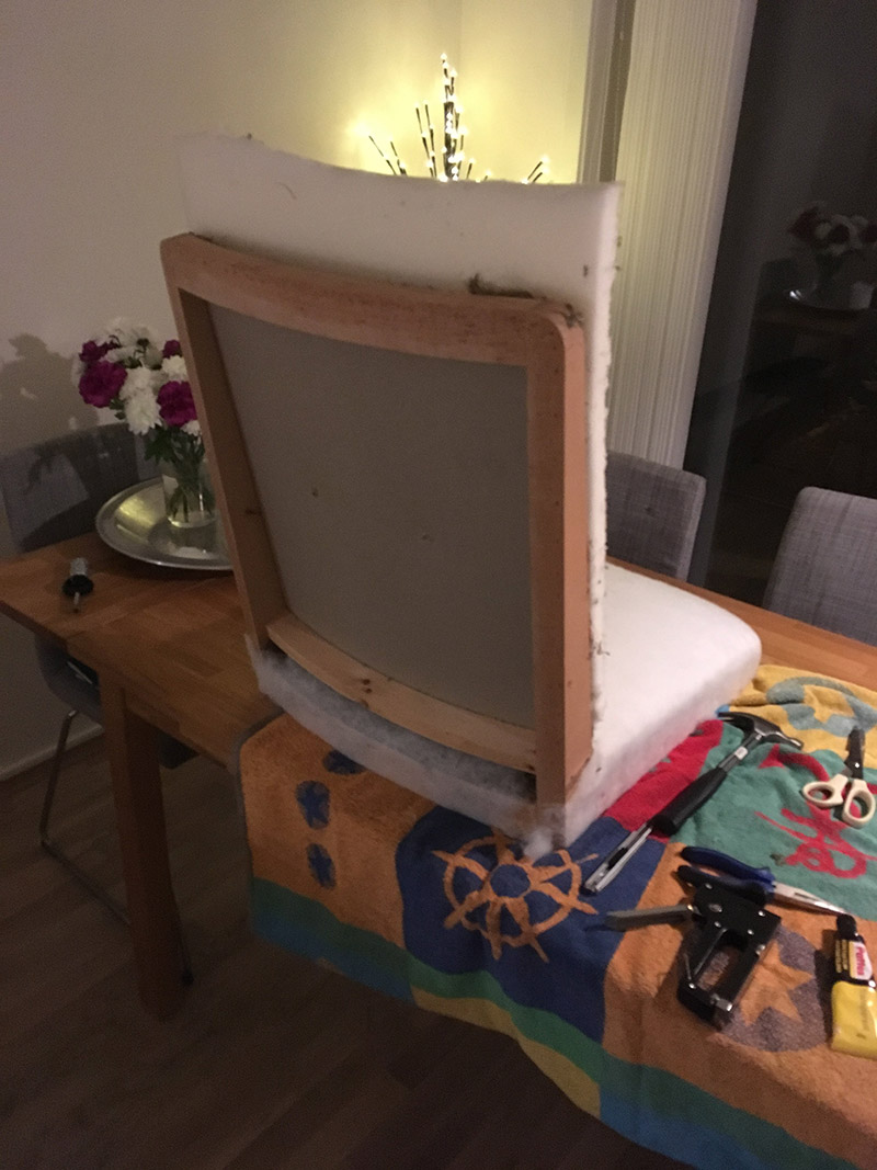
After I was satified with the foam, I began working on the cotton batting.
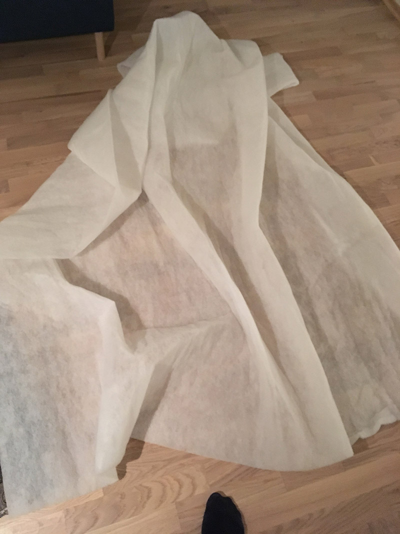
As you can see, I simply reused the old upholstery to get some rough measurements. I cut two large pieces of batting with scissors, that were more than enough to cover the back and pad. Any excess material I cut away after attaching it to the chair. It also helps having a large margin or seam allowance because the batting has a tendency to tear apart quite easily, and you want to pull very firmly on it when attaching it to the wood frame.
Having an extra person to pull the fabric does not hurt, here. At least until you can properly attach one side. I started stapling from the middle of one side, pulling, holding, and stapling. I continued this process towards each corner, but would stop around 10 cm from each corner. Then, I switch to the opposite site, doing exactly the same. From the middle, towards each corner. I repeated this for the final two sides, as well. Finally, I secured the corners in a similar manner, pulling and stapling.
Some of the staples did not go all the way in. So, I used a hammer…
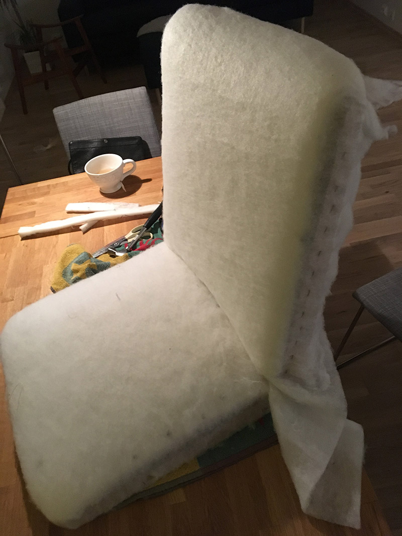
The foam on the back support is extra long, since it wraps around the top edge of the wood frame.
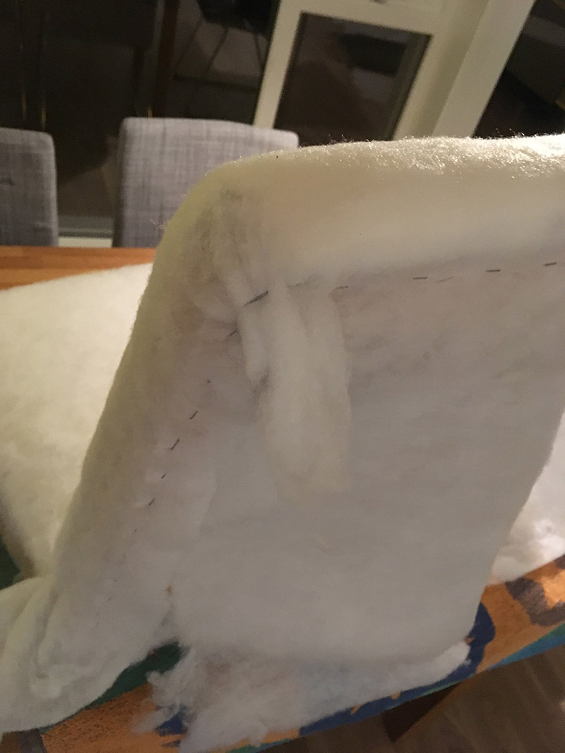
Again, I pull firmly on the batting before stapling, starting from the center of each side, and work myself towards the corners. In the picture above you see me kind of, trying to, demonstrate it on a completed corner.
As you can see, a lot of wasted cotton batting.
And finally, after having secured the batting to the wood frame, I simply cut away the excess.
Cutting the Fabric
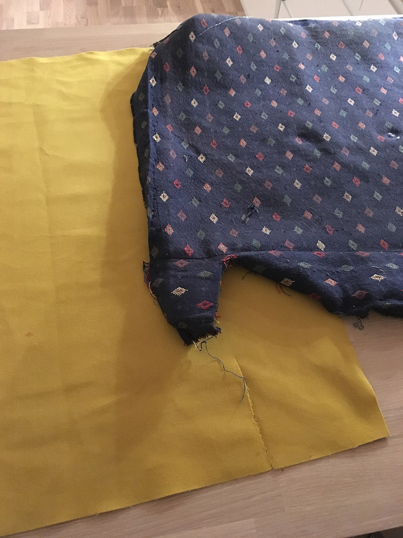
Basically repeat what you did with the cotton batting, but with much more accuracy. As you can see below, I utilized the previous fabric to measure up and cut the new fabric. I did leave a slightly larger seam allowance, just in case.
There is not that much magic to it.
Attaching the Fabric with Staples.
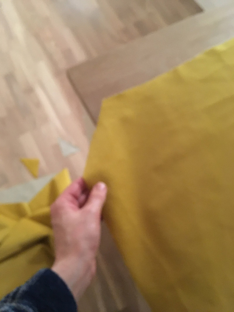
Testing the fit.
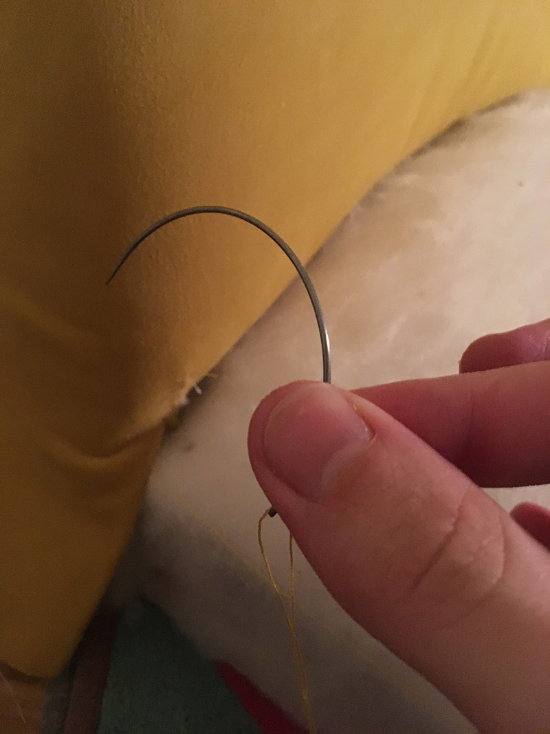
Or maybe there is a bit of magic to it. I managed to rip the fabric while attaching it to the frame, which meant I got to take the curved needle for a spin. The fabric had already been stapled to the wood frame, so it was a bit awkward sewing the rip.
The process here is exactly the same as for the cotton batting. From the middle, towards each side. Corners last. The only difference is that inaccuracies are now visible, so pull harder!
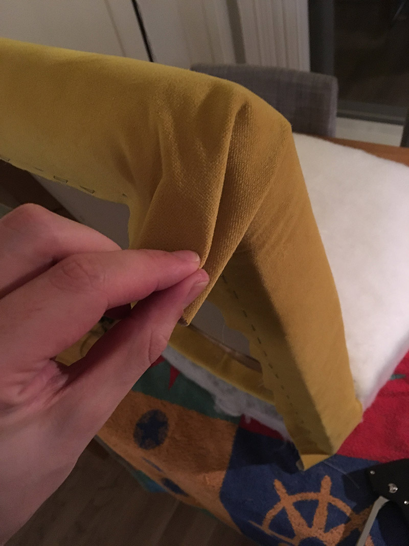
As you can see in the pictures above, I tried to fold the corners in a consistent manner.
I did end up having to cut some excess fabric. Especially from the corners.
I threaded some string on a needle, and poked holes in the fabric at around the same spots of the previous buttons. I did utilize a level and measuring tape to get the buttons on a pretty straight line.
To use pieces of electrical wire to secure the buttons was actually a pretty smart idea. Had to copy that.
You can now start to see some flaws in the upholstery work. Either I did not pull hard enough when securing the bottom side of fabric on the chair support, or I might have put too little stuffing in. Not sure why. There are also some issues on the bottom front of the chair pad.
The next step, was to reattach the cardboard plate. As you hopefully can kind of see (sorry, for the lack of pictures!), is that the fabric is wrapped around the plate, except for at the bottom. the fabric and plate were secured to the chair frame by staples and upholstery nails.
Assembling the Chair Back Together
Basically, I glued the base of the chair, and screwed the base and chair together in one go. I let the glue dry overnight.
Final Polish
Each corner has two prominent folds, that almost create hidden pockets. As a final polish I sewed these shut with yellow denim thread.
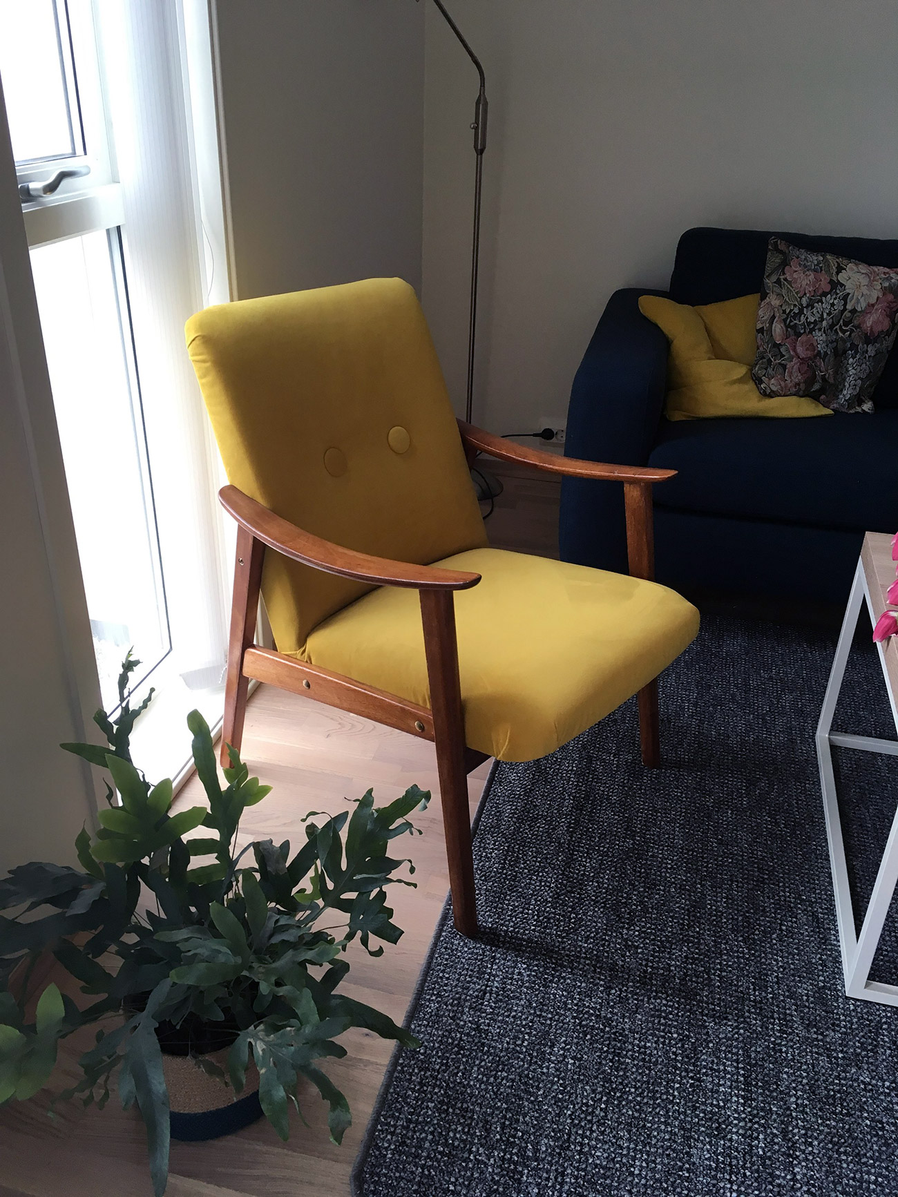
And with that, the living room became one yellow velour chair richer. It was a fun project to do, and it resulted in something unique. The chair took around a week to do, has some blemishes, but looks pretty good considering it is the work of a complete novice.
First, electronics, then software, and now woodworking. No wonder making a custom keyboard can be this exciting. In this part you will find mostly pictures of the process, including some remarks. Then, I’ll do a small conclusion of what worked and areas that can be improved upon.
Procuring Materials and Equipment
Not done much woodworking before, so I had to buy most of the tools and materials. I did manage to borrow a table saw and a miter saw. Below I’ll list everything:
Unfortunately I lost the photos taken during the frame cutting. Basically, I scribbled some measurements on paper based on length and width of the metal plate. I adjusted the measurements to allow the plate to be inserted in a 2-3 mm groove in the frame.
The thickness of the oak plank will also influence these measurements. I only managed to find an oak plank that was 1,8 cm deep.
Finally I had to decide how deep the box should be. I ended up with 3 cm, which left some room for the lid.
As you can see from the scribbles, I’m not that good at planning. Had to do some improvisation along the way.
I used the table saw to cut apart a 3cm piece from the oak plank. Then, I cut a 0.9 cm groove along an edge with the table saw. This will allow the lid to be flush with the frame.
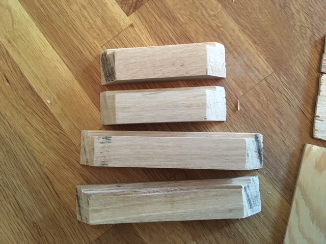
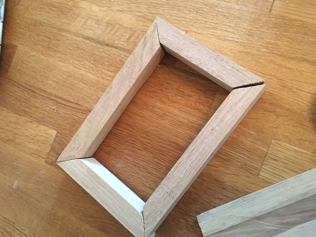
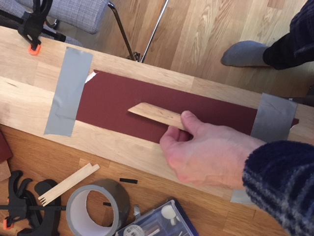
With the measurements tweaked and finalized, I cut the fairly long piece of wood with the miter saw on a 45 degree angle.
This was not easy to get right. The wood was hard to cut, and I got a lot of tearout. I added some electrical tape to reduce this.
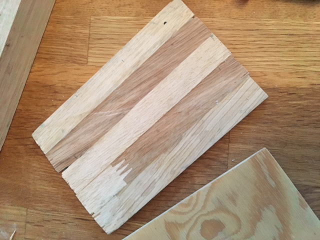
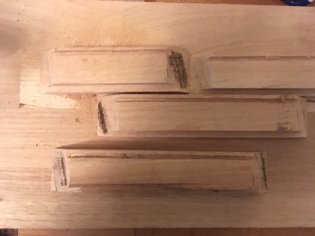
To create the lid I cut a really thin 0.4 cm piece from the oak plank. This piece was then parted into fitting lengths. Later these thin pieces were glued together, forming the lid.
Metal plate groove
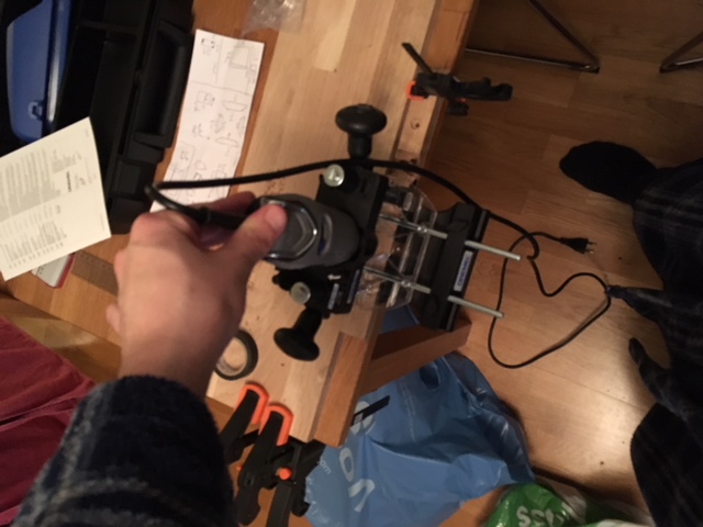
This is the reason why I bought a dremel and a router attachement. I needed some extra precision to carve out the grooves.
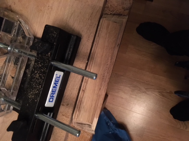
I tested the router attachment first on a discarded piece of oak to get a feel of the device, and how to use it.
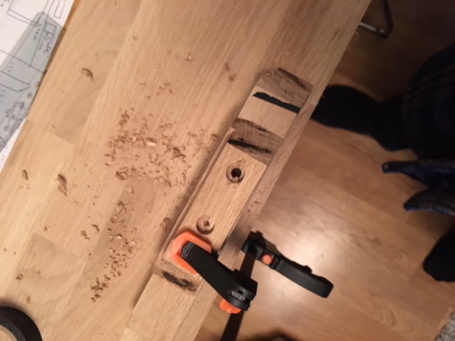
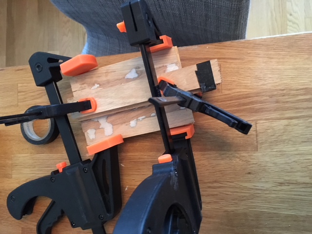
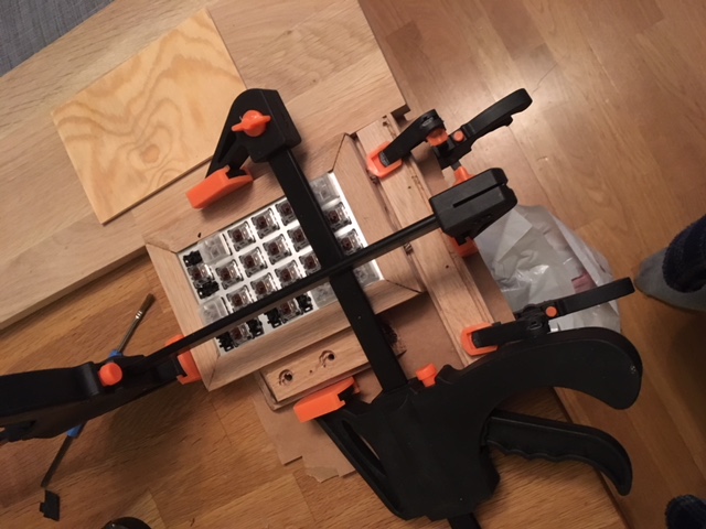
Unfortunately, I forgot to buy proper router bits for the dremel so I went over the wood in several passes with a bit that looked router-y. I clamped down the remainder of the oak plank and a discarded frame piece to my kitchen dinner table to keep the frame pieces from moving when cutting the groove. Luckily, it worked out well!
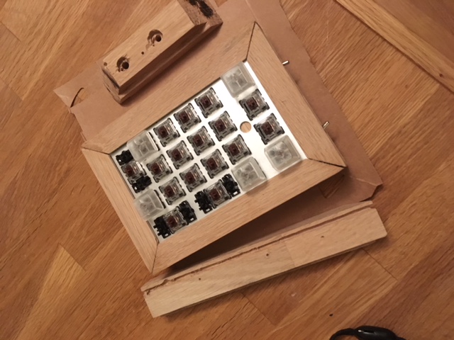
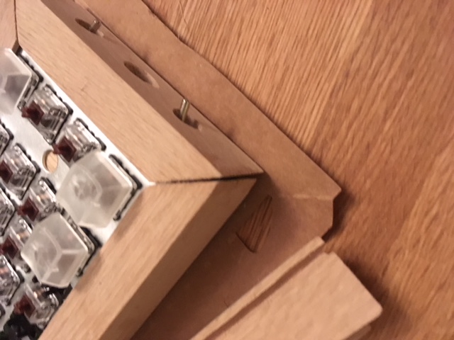
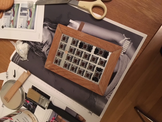
This allowed me to test the fit of the frame. Not a perfect fit, but good enough.
Drilling holes for the USB and Switches
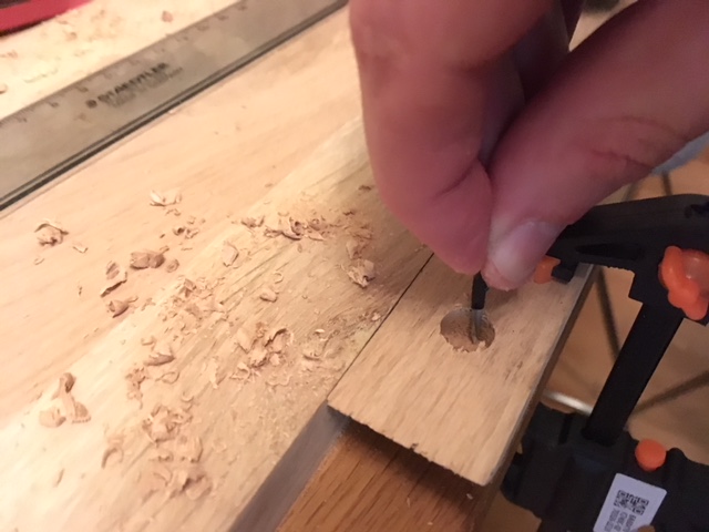
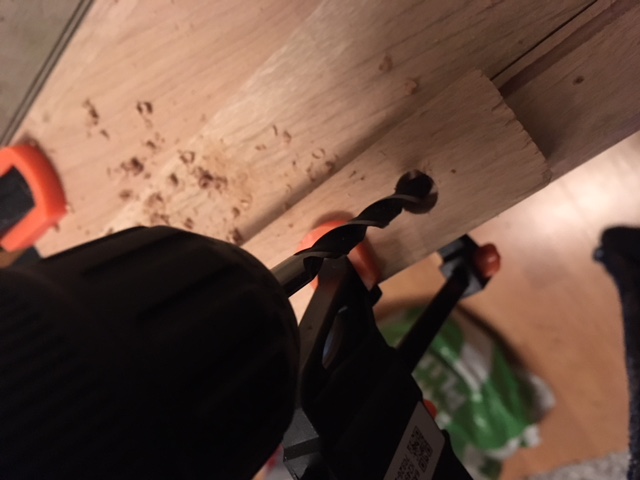
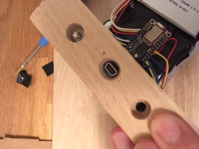
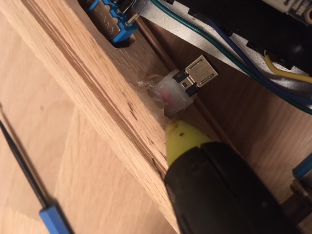
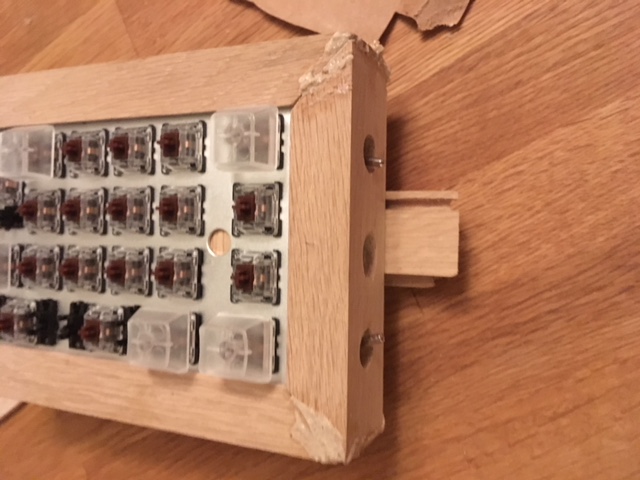
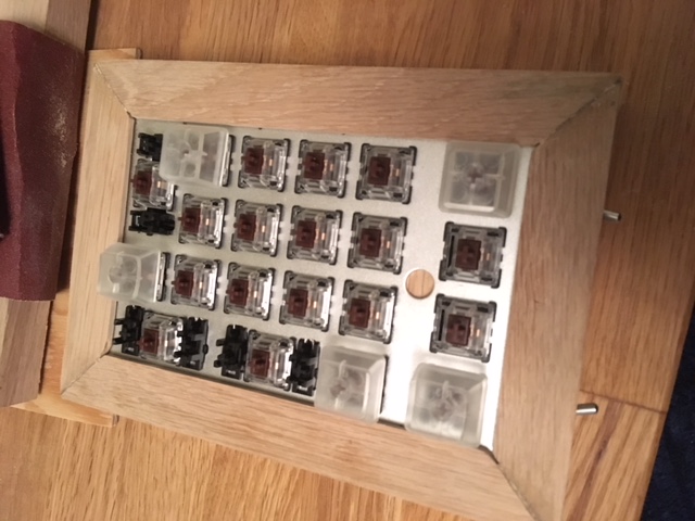
In one of the frame pieces I had to droill three holes. Two for the switches and one for the USB. The frame is pretty thick, so this meant a lot of carving and drilling. This was also a bit nerve wracking, since any errors would most likely be very visible, and could result in me having to cut a new piece.
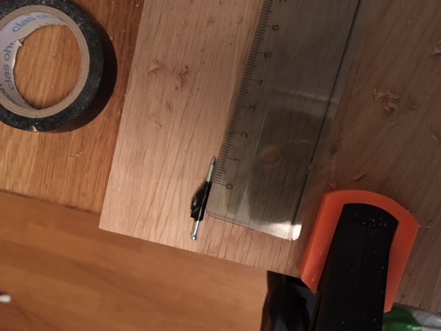
First, I marked the spot where I would drill a 10 mm hole about halfway in. I used a nail with some tape to ensure I would not drill to far in.
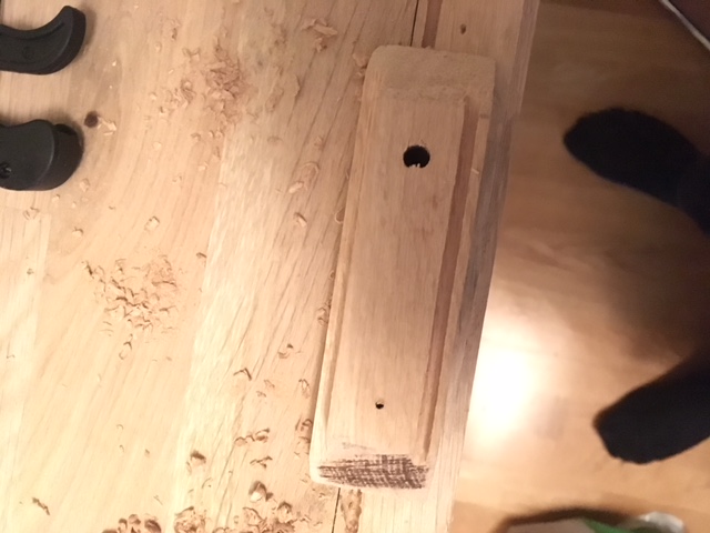
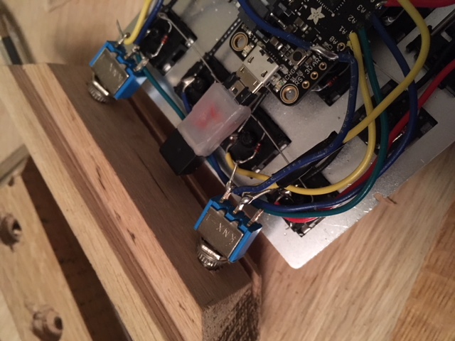
Then I switched from a 10 mm bit to a 6 mm bit and drilled all the way through. The neck of the switches is threaded and can be secured with a small fastener.
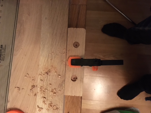
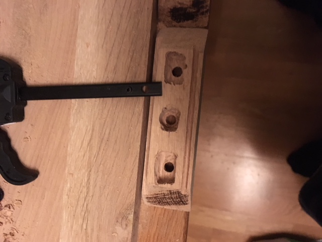
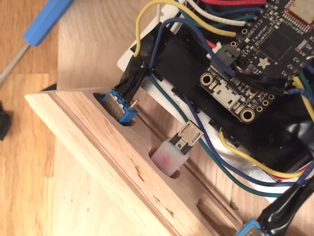
As you can see in the picture above, the threaded neck was not long enought to fasten on the other side. This meant I had to carve out an area from the inside of the wood piece. In the picture below a 10 mm hole for the USB connector has also been drilled. The router attachment came in handy here as well.
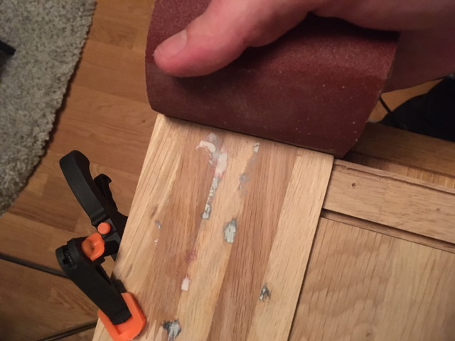
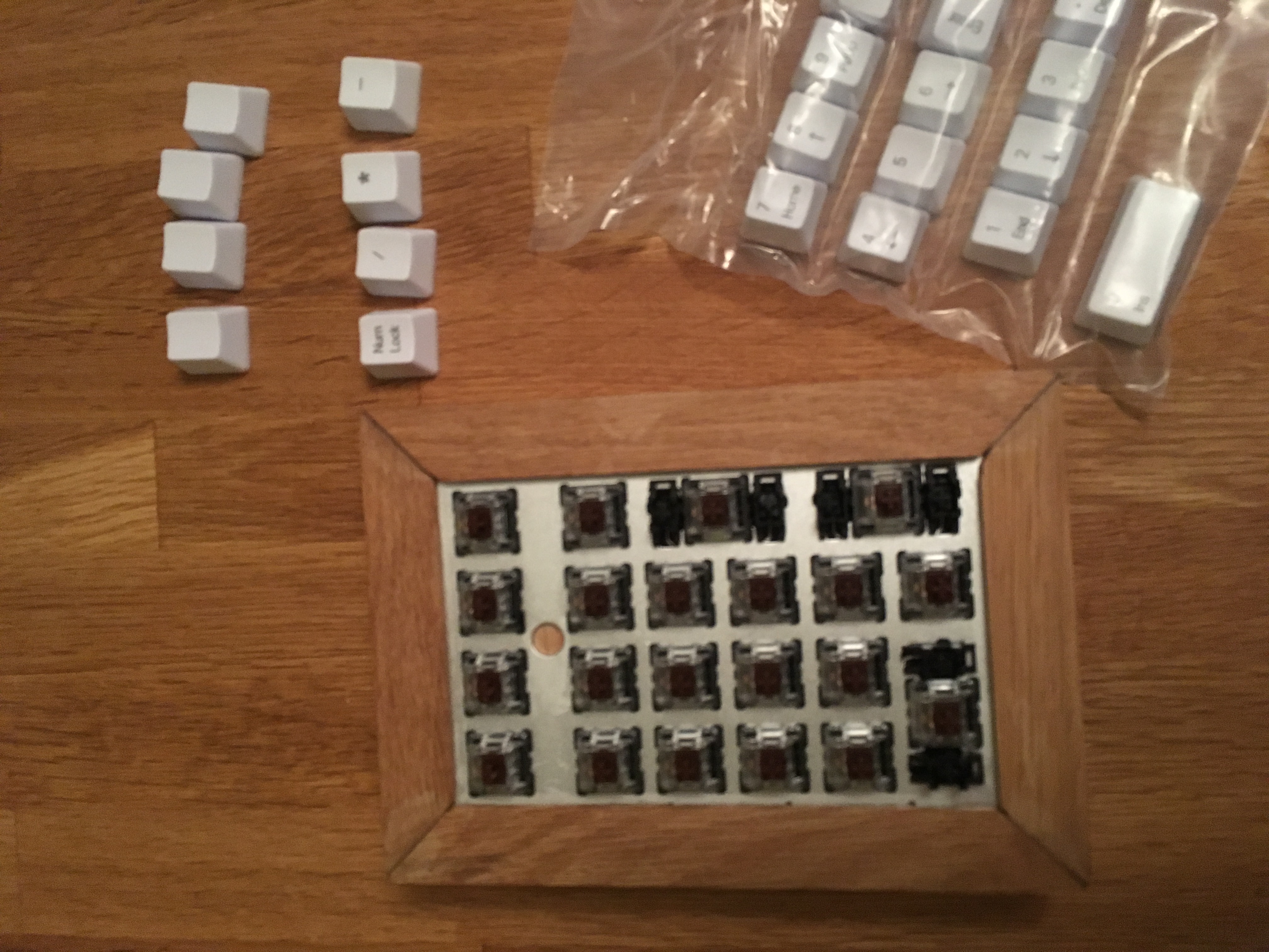
Finally I did a lot a sanding of all the pieces, including the lid.
I also added some electrical tape to separate the hand-wiring from the MCU.
Gluing the Mess Together
First, I glued a small piece of wood to close of the hole in the metal plate.
The lid had to be glued together.
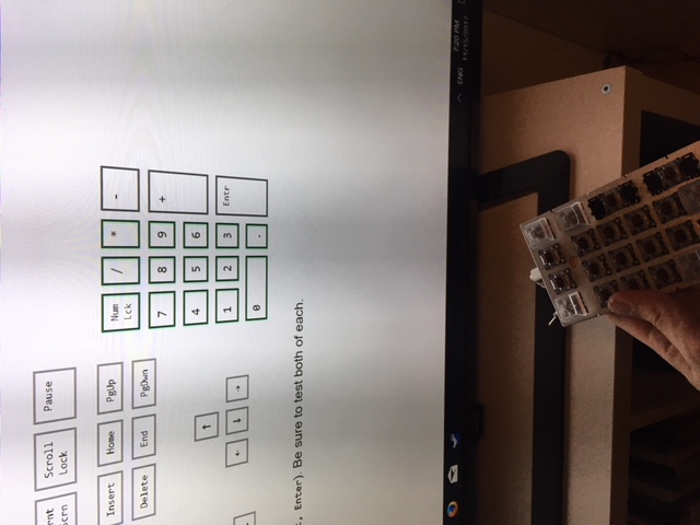
I, of course (did not almost forget), to test that the numpad still worked before gluing the frame to it. Testing numpad by connecting it to a computer and verified that all keys still worked using keyboardTester.com. The F13 and up keys were tested at this site.
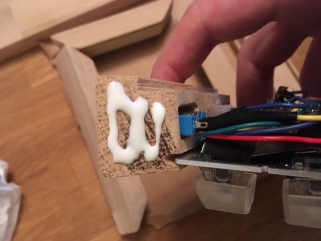
The switches and the USB was fastnened to the top piece. Hot glue was used for the USB connector.
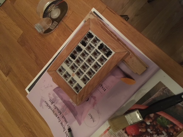
Then, a final test of the frame. It fit, but not perfectly. Some gaps. Might have appeared because I sanded all the 45 degree surfaces. I probably should have avoided that.
Applied wood glue to all 45 degree angled surfaces. Should have used tape here to avoid glue squeeze out. But forgot, of course.
Finishing Touches
I noticed that the frame had pretty large gaps after the glue had dried overnight. I made some wood filler by mixed some of the sawdust with glue, and tried to fill in the gaps.
I glued the metal plate to the frame with hot glue.
Coated the frame and lid with hardwax oil. Did that twice.
Securing the Lid
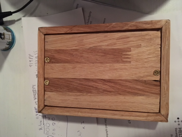
After gluing and coating the frame and lid, the final thing left to do was securing the lid to the bottom of the frame.
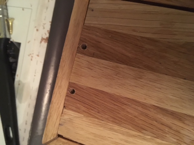
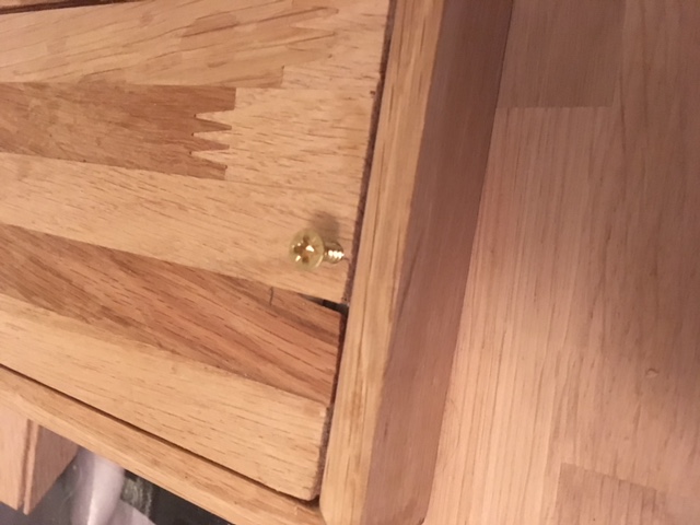
I drilled 3mm pilot holes in the lid and down into the frame. Done to prevent wood from cracking, and since the screws are really close to the edge of the lid and the frame.
Furthermore, I had to sand away a bigger diameter around the holes to make the screw heads flush with the lid surface.
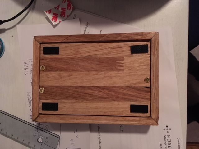
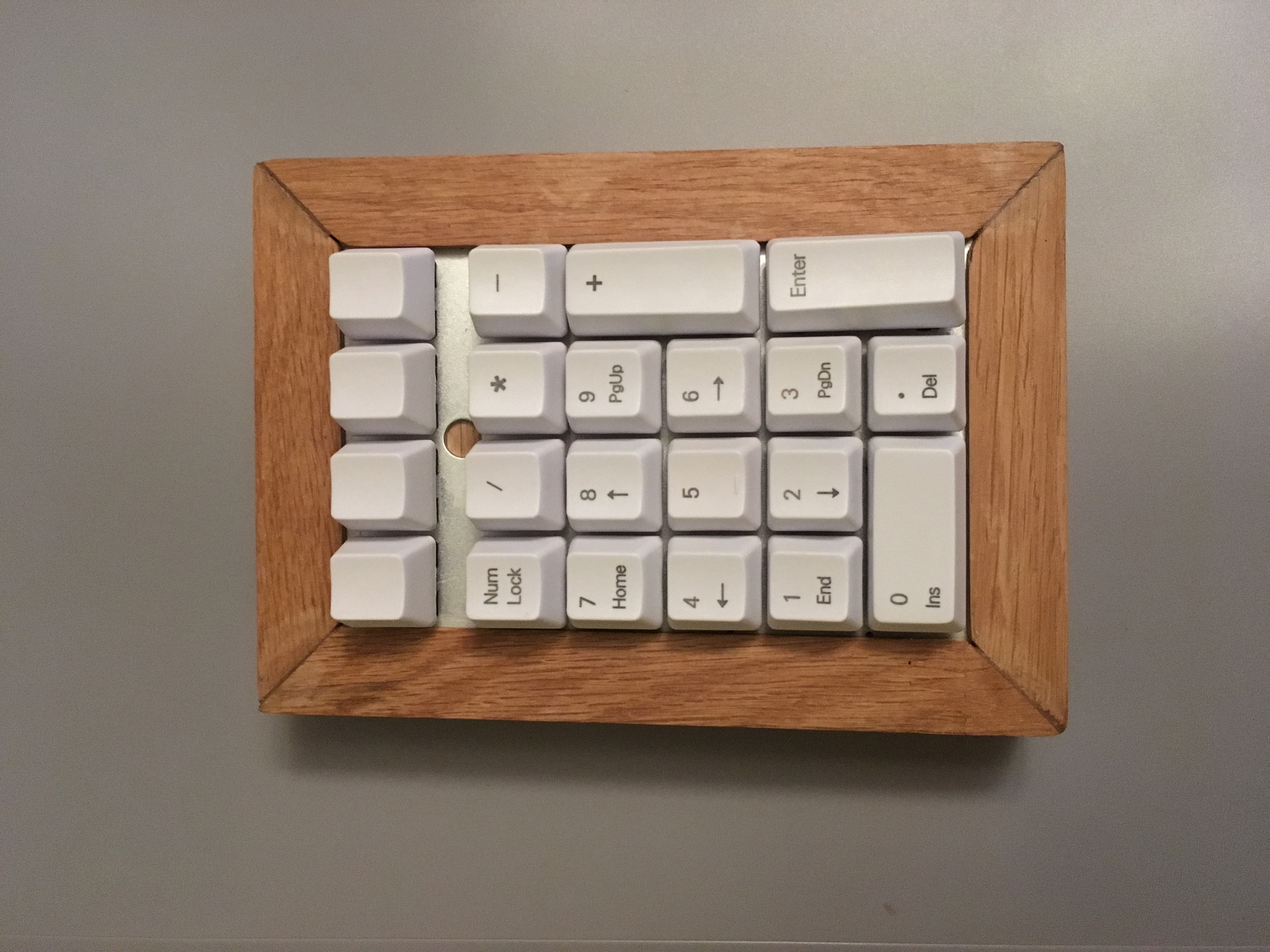
Found some adhesive rubber feet lying around, so I applied them to the bottom of the numpad. The device is finished. In it’s final form. The only thing missing now is adding some key caps to it.
The key caps came in the mail a week after. Ordered them from AliExpress.
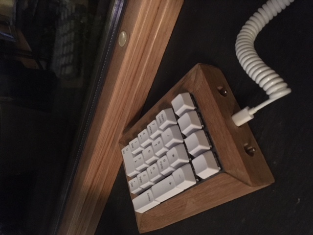
A short video of the device in action, can be found here.
Conclusion
In conclusion, I would say the numpad is functional. It works. However, there are a lot of things that could have been improved.
First, the software is a bit unfinished. For instance, handling a press-and-hold of a key. I might do that in the future. Or somehow use existing keyboard software ported to Arduino.
The frame is also a bit wide for my taste. Originally, I aimed at an 1 cm wide frame, but had to later adjust since I did not find any oak material with that thickness.
Not sand the angled surfaces, or be more careful when doing that.
Adding a blue led to indicate if the numpad is in USB or Bluetooth mode would have been nice to have.
I could also have removed the switch that switch between USB and Bluetooth. This could have been done with a special numpad key combo that I could include in the software.
Including the tools and material bought to do this project, it is one expensive numpad! However, can’t set a price on having fun. Plus, productivity in Excel will go through the roof with this device!
This is part two of the build log. Now we turn to the software, which are gonna make this thing act as a numpad when connected to a computer. The code that runs the numpad can be found at this repo.
Configuring the Arduino IDE
To load the software onto the Adafruit Feather 32u4, you’ll need the Arduino IDE. Out of the box the IDE does not support the Feather, so follow the setup guide to install the Adafruit board manager.
After you’ve installed everything, you can test the board with some of the example scripts to check that the board is working.
Simple Numpad Scanner Script
I implemented my own matrix scanner. First, to get a deeper understanding of how the matrix works, but I ended up later converting it to a library, that the main sketch utilizes to scan the numpad.
The scanner code was shown in the previous post (and can be found on GitHub, here). Note that I mixed up row and column. For instance, the activateOneRow should have been called activateOneCol. This mix-up was fixed in the library code, so please look at that if this code is confusing.
The code snippet has been left there to illustrate how I progressed from an empty sketch to a working HID numpad.
Converting a Script to a Library
Putting all the numpad code, in addition to the Bluetooth and USB code in one sketch would quickly turn messy and unmanageable. However, I had no prior experience with C and C++, so writing the library was challenging. I used this Arduino guide as a reference to write it.
I’ve mostly spent my time in languages such as JavaScript, Python and C#, so writing C++ was interesting. Below is a list of issues I had. I spent quite a bit of time on some of them.
Pointers.
Returning arrays from a method was not that straightforward, because of the point above.
Memory management felt a bit foreign.
Worrying about running out of memory.
Serial object not initialized before setup(), so calling print does not work, and using Serial to determine if board is connected to USB did not work.
However, I did create a library of some sort. If you want to use it, remember to put it into the /Documents/Arduino/libraries folder to use it in the Arduino IDE. In the section below, you can find a tip related to that.
Below I’ll quickly explain the public methods:
scan() - Scans matrix and records pressed keys.
getPressedKeys(int i) - Returns one of the pressed hexadecimal integer key code.
getNumberPressed() - Number of keys that have been pressed.
The methods above are defined in the Numpad.h header file. The header file also defines a matrix of hexadecimal integers that represent HID key codes. A table of all available USB HID codes can be found here.
I also tried implementing some sort of delay between the first and second character press, but here I failed. Instead, when you press and hold, only one character is sent. You will have to release and press again to send another character to your computer. This alternative approach works well enough for a numpad.
Symbolic Links
Arduino unfortunately likes to have all its libraries in /Documents/Arduino/libraries. This is a bit inconvenient when developing a library. In the beginning I did a copy and paste of the library from the code base into the libraries folder, whenever I did a code change. Did not take long before I got tired of doing that, and found a better way.
The solution is to create a symbolic link. Arduino will then always use the up to date library code from the code base.
How to creating a symbolic link:
Open cmd.exe in administrator mode.
Create a symbolic link by: mklink /D "C:\Users\equalpasta\Documents\Arduino\libraries\Numpad" "C:\Users\equalpasta\Documents\git\arduino-bluetooth-numpad\Numpad"
Power Switch and Battery
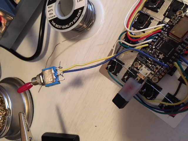
Since I will connect a battery to the board, I soldered on an on/off switch. This is done by connecting the ENABLE pin to GROUND through a switch. If the circuit is closed, the device does not operate. See here for more information.
Bluetooth and USB Connectivity
The HID keycodes are either sent over Bluetooth or USB.
Bluetooth
Utilized example code that can be found on the board’s website. The HIDKeyboard example shows how to set up the board as a HID device, set the broadcast name, and how to send key codes.
I created a small wrapper for the Bluetooth code.
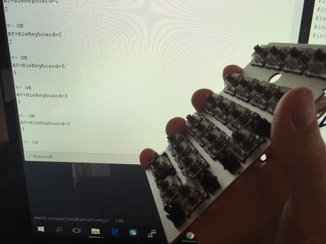
Basically, you use ble.print to send AT+BLEKEYBOARDCODE=00-00-00-00-00-00-00-00 commands. The latter 6 groups of number specify up to 6 simultaneous key presses.
After each of these you need to “release” the keys by sending an additional AT+BLEKEYBOARDCODE=00-00 command.
USB
As specified in the Arduino reference, 32u4 based boards can become a HID device. It also mentions NicoHood’s HID library that implements different HID devices.
I used the Improved Keyboard HID library.
Add Keyboard.begin() at the top. Sending codes are done by: Keyboard.write(KeyboardKeycode(numpad.getPressedKeys(i)));. getPressedKeys returns hexadecimal integers.
An Additional Switch for Bluetooth/USB
Originally, I planned to switch between Bluetooth and USB connectivity based on whether the USB/Serial was connected. This turned out to not be as easy as I thought:
Checking if Serial is initialized or not can work. Unfortunately, this check cannot be done in setup since Serial is not necessarily instantiated before setup is run.
No easy way to detect USB/Serial disconnect event.
You might want to charge board, while sending keystrokes over Bluetooth. So, you need to determine that the board is connected to a computer.
Basically, I ended up soldering on an additional switch, that controls how the numpad sends pressed keys. In each iteration of the loop method, switch is checked and the pressed keys are either sent over Bluetooth or USB:
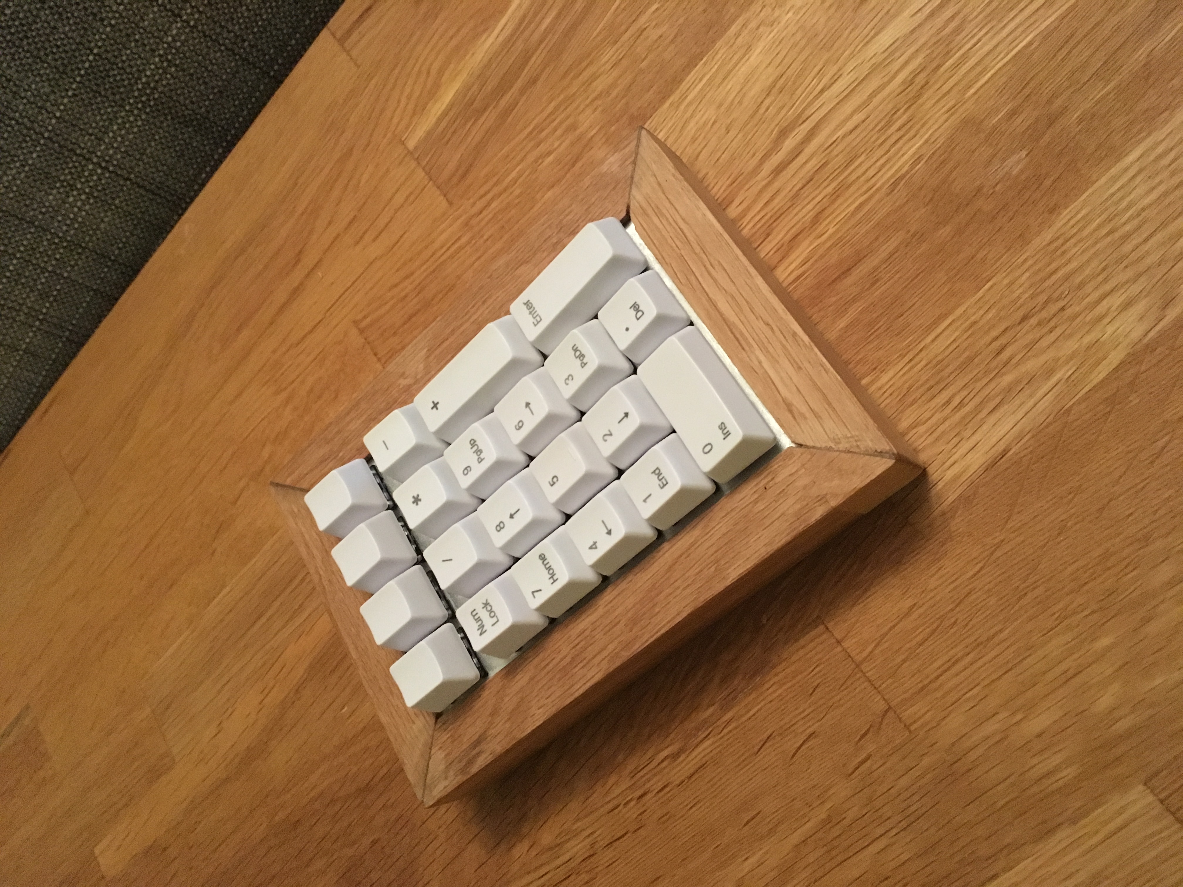
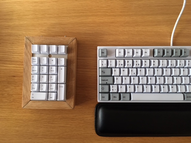
The best way to begin this post is maybe with an after photo. So here it is:
This was a fairly large project, so it made sense to split it into three posts. Each part goes into the different aspects of this project. Electronics, software and woodworking.
I ended up upgraded my keyboard to a mechanical one a couple months back. A quick and simple purchase, I thought. Oh boy, I went way down the rabbit hole on this one, reading obsessively about the tactile feedback of different switches, of the ergonomic advantages a TKL keyboard can provide, and really, just spent a lot of time looking at pretty keyboards on the subreddit for mechanical keyboards. I even bough a switch tester.
At first I wanted the impossible:
A TLK keyboard
ISO layout
Good build quality. Preferably with a white/grey key and base
And Bluetooth and usb dual connectivity
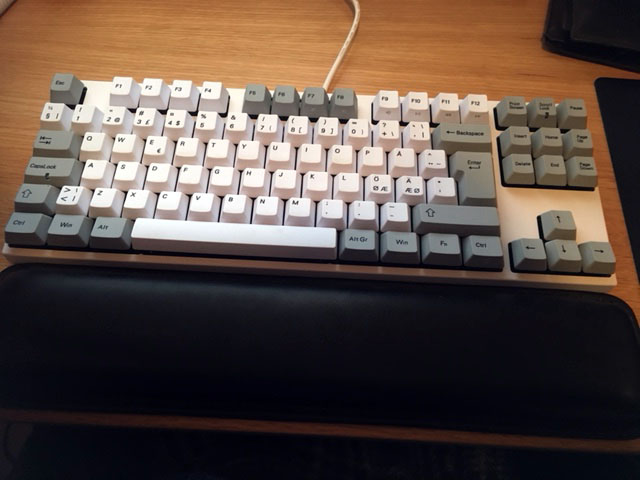
There are already few ISO layout keyboards out there, but it was the latter point that made it impossible. At one point I strongly considered creating a keyboard from scratch. But in the end, after weeks of trawling through options, I ended up buying a Varmilo VA88M. No Bluetooth, though.
The keyboard is missing a numpad, as you can see, which is ok 90% of the time. But, sometimes you need to input a lot of numbers, and that is when I really miss it. That gave me the idea to create my own Bluetooth numpad. A device you can easily remove from your desk, when not in use. Perfect!
And by the way, this is my first experience with electronics, soldering and so on. The guide might, therefore, be helpful to other novices out there.
Buying the Parts (and the Long Wait)
Since I’ve had no prior experience with electronics, I had to buy a lot of stuff. I’ll create two lists below. The first will list some essentials for electronics work, and the next will list components needed to create the numpad. By the way, buying things off of eBay can be a slow affair, especially when it ships from China.
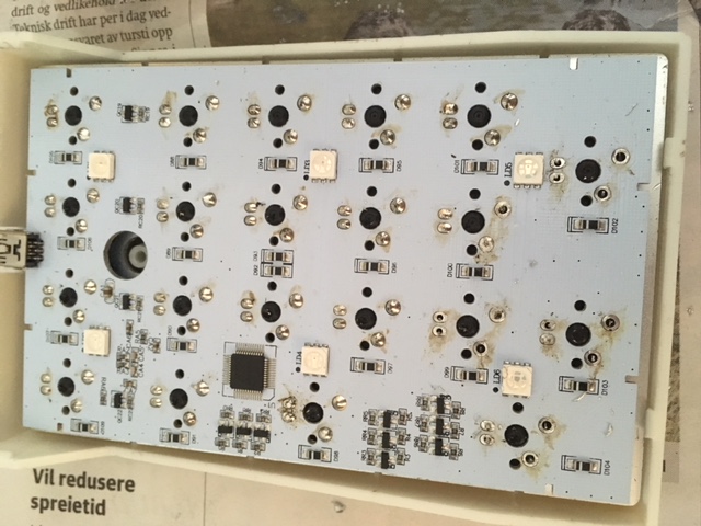
The plan is to hand wire the keyboard matrix to the Adafruit microcontroller. Unfortunately, the donor numpad came pre assembled, which meant I had to desolder it. This was the first time desoldering, so I was glad I did not need to keep the PCB. Before I began I watched a couple of youtube videos on how to desolder and solder (1, 2). In addition, I read the amazing soldering is easy comic by Mitch Altman, Andie Nordgren, and Jeff Keyzer.
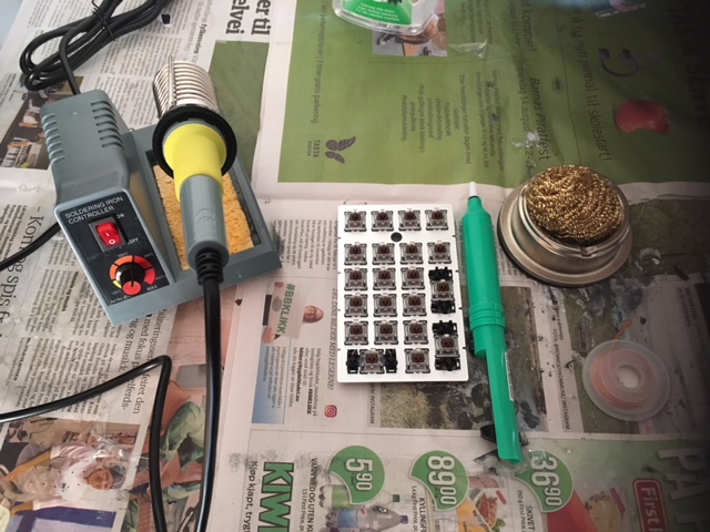
Prepare the Equipment
Heated the soldering iron to around 370 degrees Celcius. Soldering wire is missing from the picture below. Safety goggles was also equipped at this point.
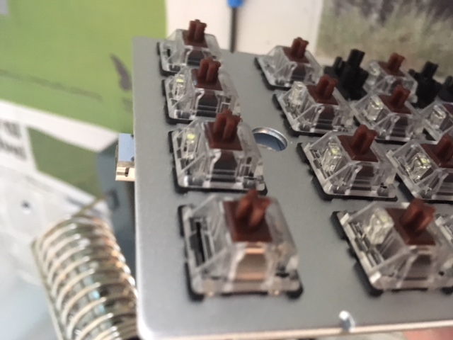
We want to desolder all the switches and LEDs from the PCB, in order to free the metal plate from the PCB. We will later hand wire the switches to the microcontroller.
Each switch had 4 through-hole connection points. 2 for the LED and 2 for the switch. With 21 keys in total you need to do a lot of desoldering.
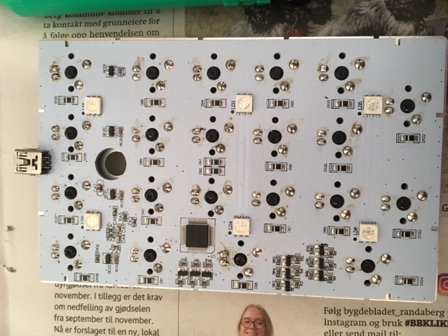
Melt All the Solder!
It will probably take some tries before you get a good technique on how to melt the solder and remove it with the soldering pump before it solidifies. I found that the most effective way was to add a bit of solder to the connection to properly melt to solder. When it melted I would quickly and forcefully put the tip around the hole to form a vacuum before sucking the solder into the pump.
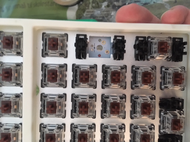
At some connections I failed, by only sucking out some of the solder. Typically caused by not getting a tight seal around the hole with the solder sucker. In those instances, I would add fresh solder to the hole and try again. In addition, to pry loose the switch and LED pins, I lightly wiggled the pins using a metal pick. With the switch pins free, I then applied pressure to pop the switch out.
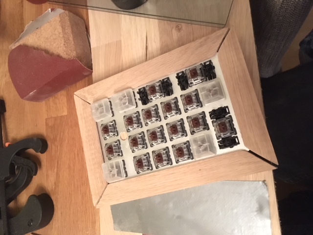
Store Components
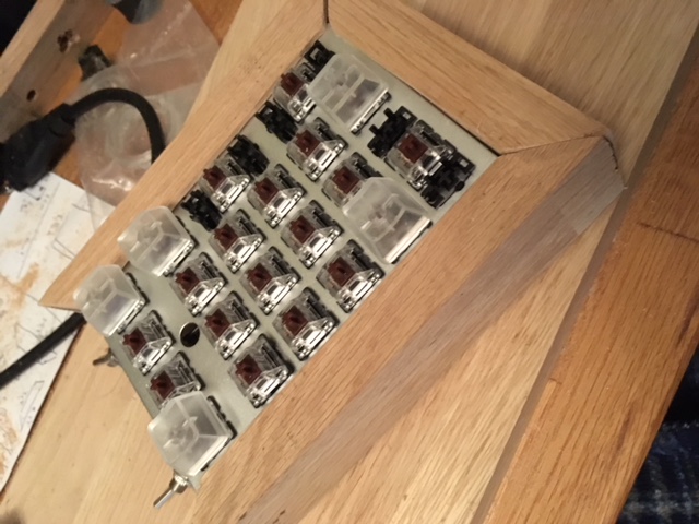
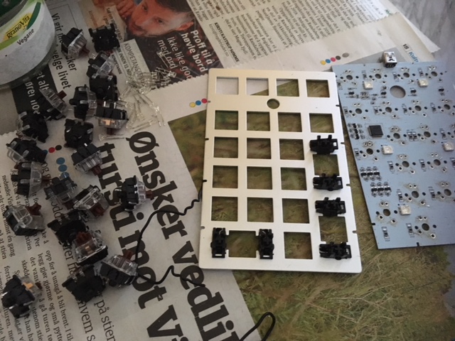
Below, you see the finished result. 21 switches, LEDs, and the metal plate. Most of the parts will play a part in the next section, when we hand-wire the switches back onto the metal plate.
The Keyboard Matrix
On a numpad you want to end up with 4 rows of wires connected to all switches, and 6 column connections to all switches through diodes. A good explanation of how a keyboard matrix works can be found here and here. Make sure you somewhat understand the theory before beginning. I’ll show a side by side comparison of the finished circuitry and the keyboard matrix diagram below. I mixed up row and column a bit when testing the numpad in the Arduino IDE, so an image as below would have been useful.
R1 to Rn should each have a pull-up resistor (often integrated in the MCU) which keeps the input at HIGH if switches in that row were not pressed and LOW if any were pressed. Each column is scanned one at the time, when reading which switches have been pressed. This happens very fast so this iterative scanning is not noticeable. For instance, when C2 is scanned, C2 is set to LOW, and input R1 to Rn are read. If switch C2-R1 is pressed, it will close the circuit from R1 to C2 (ground), and make the input R1, LOW. Please read the links to get much better and more detailed picture of how these matrices work!
Hand Wiring the Numpad
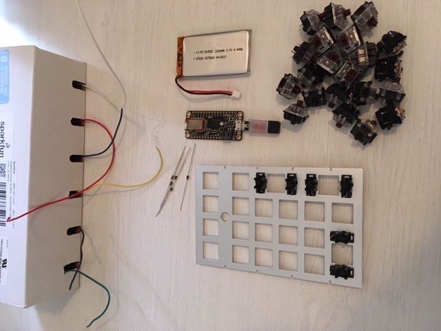
While doing this step I followed this guide, closely. You’ll need diodes, wire, the metal plate, stabilizers and switches to do this step.
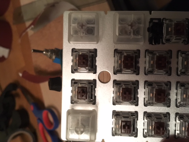
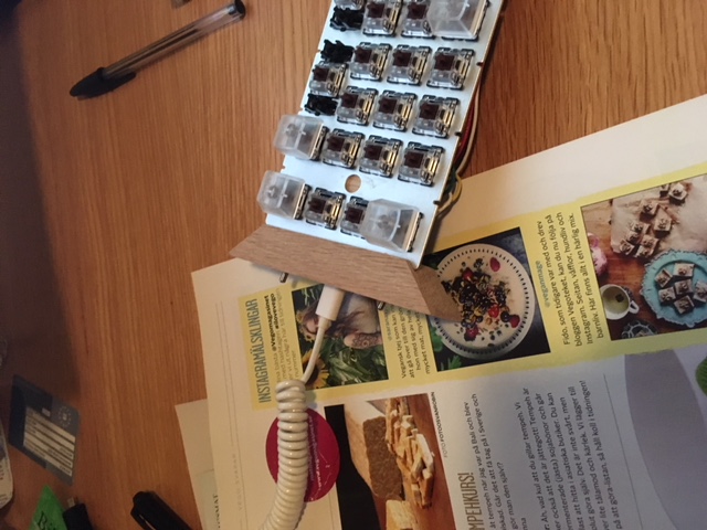
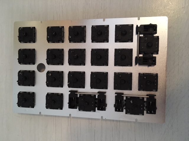
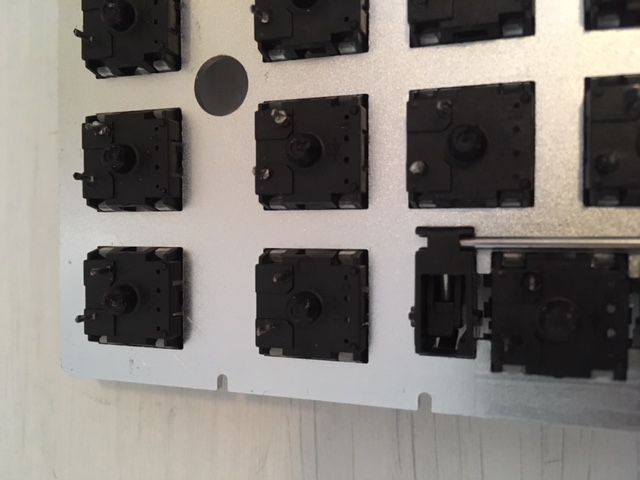
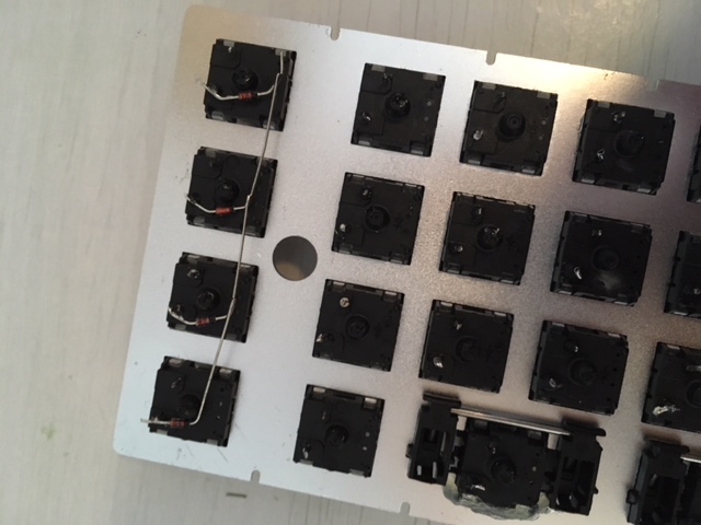
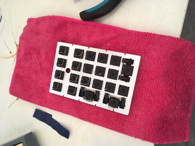
Pop the switches and stabilizers into the numpad plate.
I had to glue some of the switches to the plate, but most fit snugly into the plate. Remember to place all the switches in the same orientation, as you see in the picture below. Though, I believe the switches are bidirectional.
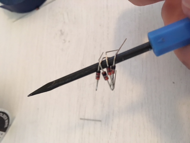
I then bent the diodes into shape. Did it for 5-6 diodes at the time. Bending the diodes using a pick tool was much simpler, and resulted in sharper angles.
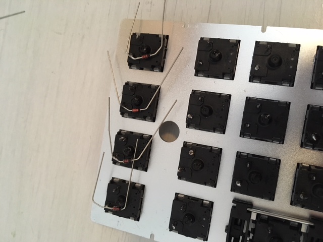
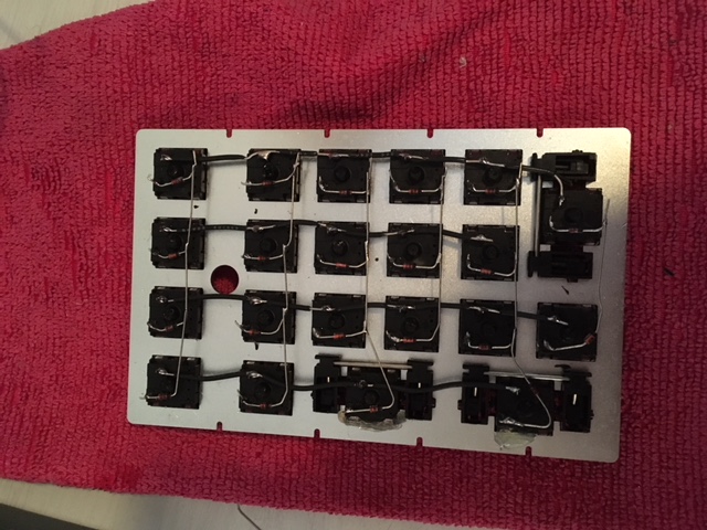
Then you solder the bent diodes to the top most connection of the switches in each column. A soldered column of diodes can be seen below. Note that the black band (cathode) must be placed correctly. It has low resistance to current in one direction but not the other. So do this carefully. You see how the diodes are soldered on below. Below the switch pin with the black band away from the connection.
Another tip when soldering, is to start off by add some solder to all the switch pins. Then, place the diode correctly, touching the pin, and heat up the solder that is already on the pin.
Connect the diodes to the pins, and then solder the diodes together as seen below. After that has been done, it is a good time to use a wire cutter and remove excess wire.
Two and a half columns done!
All diodes soldered on. As you see, all the diodes in one column are connected. And the direction of the diodes are correct.
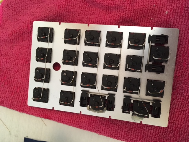
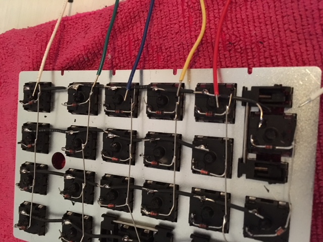
Then you need to prepare the wires that will go to all the switches in each row. I trimmed the ends and used a small knife to trim away the shielding from areas of the wire where the middle pins are located. Try to remove the least amount of rubber shielding, since rows and columns will cross each other, and possibly touch.
First row wire soldered on.
All row wires prepared and soldered onto the numpad.
Connecting the Bluefruit MCU
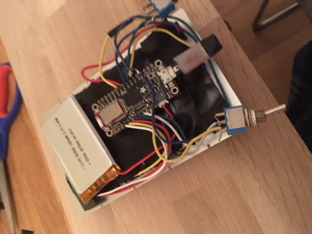
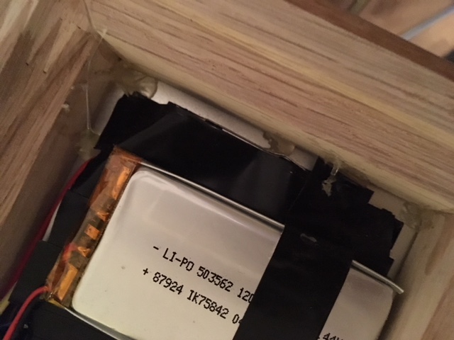
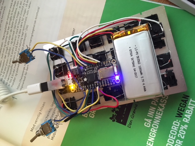
The matrix itself is complete. The only thing left is to connect the matrix and the microcontroller. The plan is to stack the microcontroller and the battery on top of the matrix. This will, unfortunately, result in a slightly fat numpad.
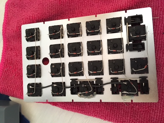
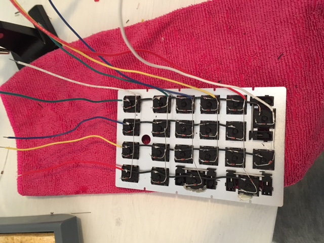
As you can see below, I was a bit generous with the wire. First I connected the end of each column to a wire.
Then I connected the left most switches in the row with wire.
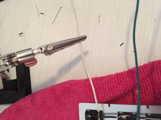
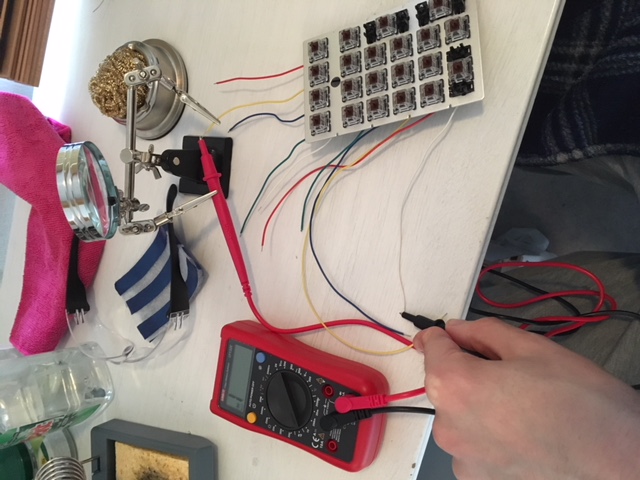
A helping hand stand proved very useful here.
Before soldering wires to the microcontroller, I used a multimeter to test continuity. It show “1” if the circuit is open, and beeps if it is closed. So each key could be tested by probing the correct row and column, and pressing the key down.
I then trimmed each wire down to avoid too much excess wire and soldered them to the microcontroller. The pinouts diagram can be used to decide which pins on the MCU you can use. You’ll need 10 general purpose input/output pins. The wires are a bit stiff so the MCU actually float a small distance above the keyboard matrix.
Finally, time to test the numpad!
Connect it to your computer. You probably need to install some drivers to enable support of Adafruit boards in the Arduino IDE. Setup guide here.
I wrote a simple script that scans the columns and reads which buttons have been pressed. It outputs the position or index of a key rather than the value of the key. Works well for testing that key strokes are registered by microcontroller.
So, the numpad basically works. However, it does not act like a keyboard yet, and can’t connect to a computer as a bluetooth device. An attempt at solving that will be done in the next post.

 The chair is pretty old, which meant that the bolts holding the chair and the base together were hard to get out. I had to apply some force to a hex key positioned at the tip of the bolt, to get them out. Once out, I cleaned the brass bolts and fasteners in a water salt and vinegar solution. Later, I applied some grease on the bolts and fasteners.
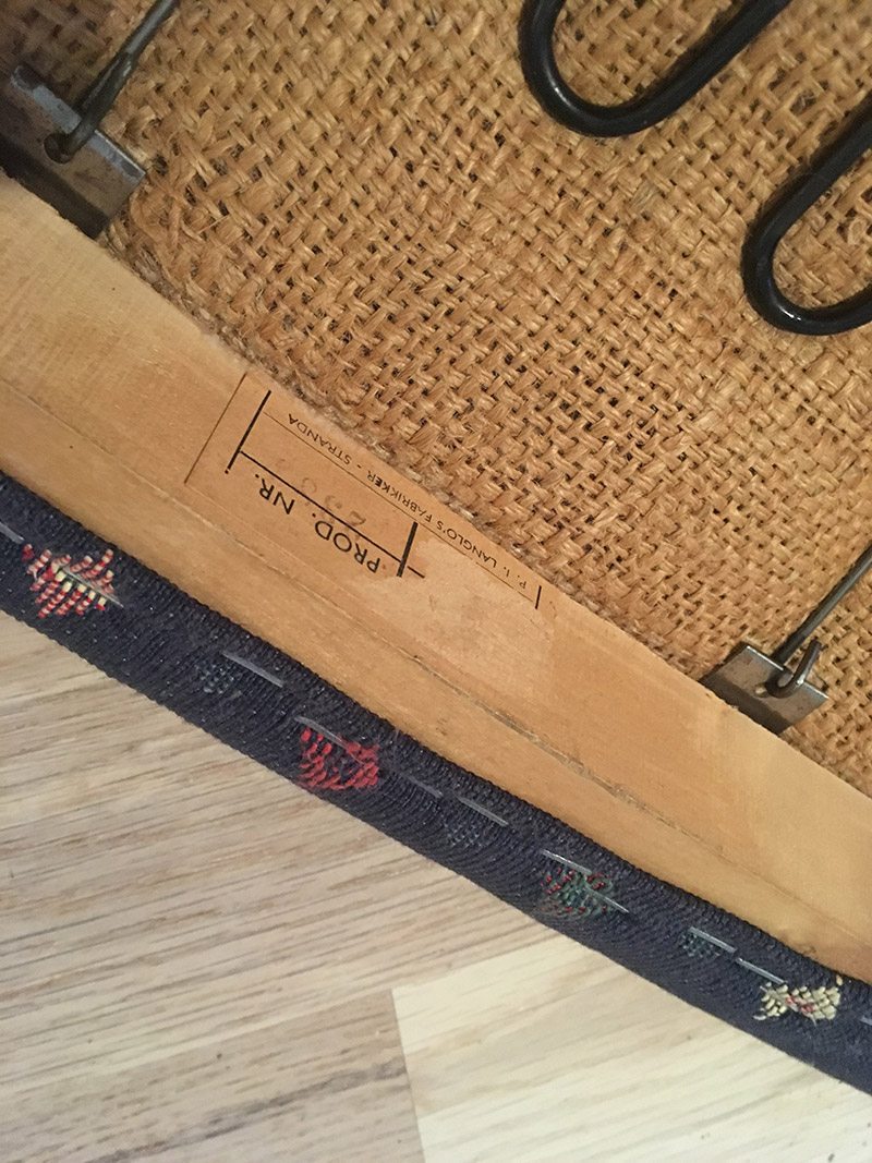 Found this underneath the chair. Product number 2383 and made by P.I Langlo factories. Nothing about what year it was produced, which I am a bit curious about.
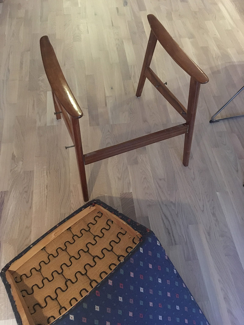
 A plate, that had a cardboard feel to it, was found underneath the fabric on the back. I managed to reuse it by carefully removing all the staples that attached it to the wood frame.
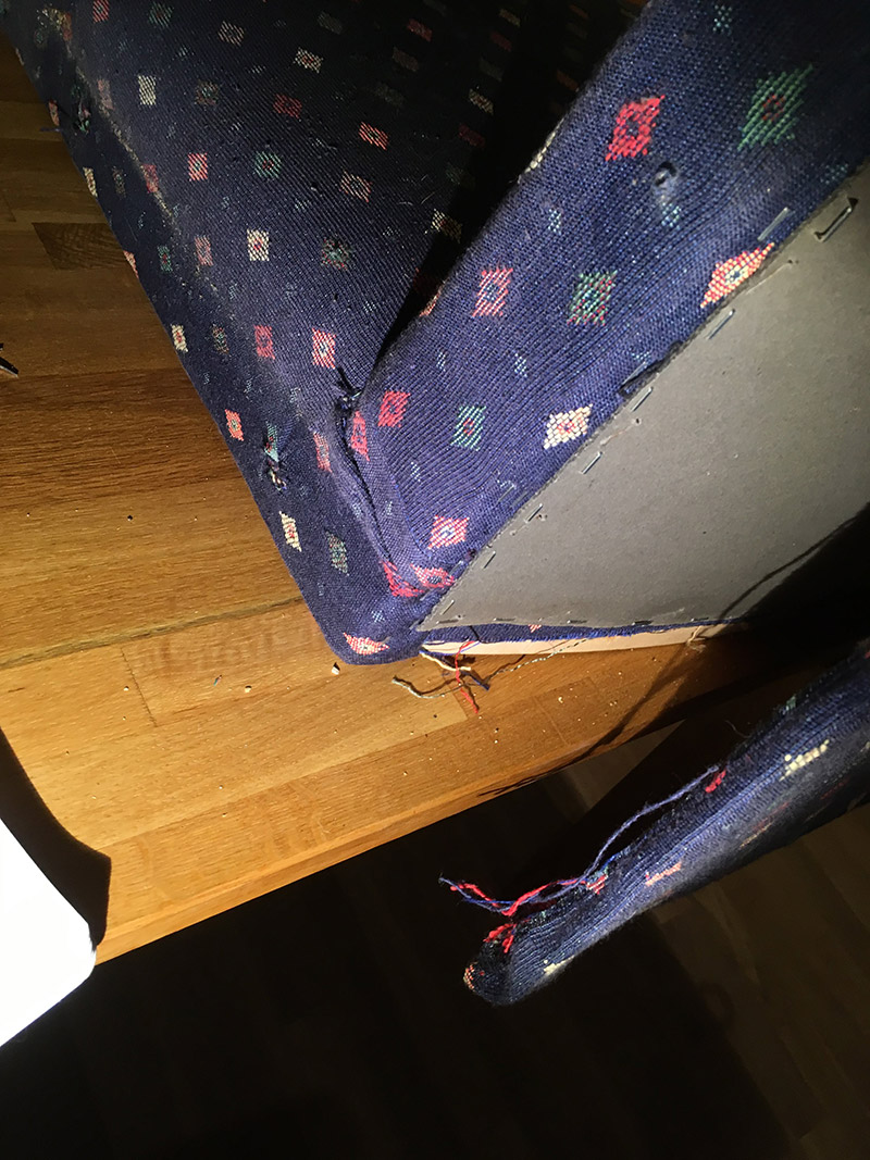
 A lot of staples. Some of the staples were quite hard to get out. In order to get them out, I first split the staple in two with side-cutting pliers, and dragged each part out with the round nose plier.
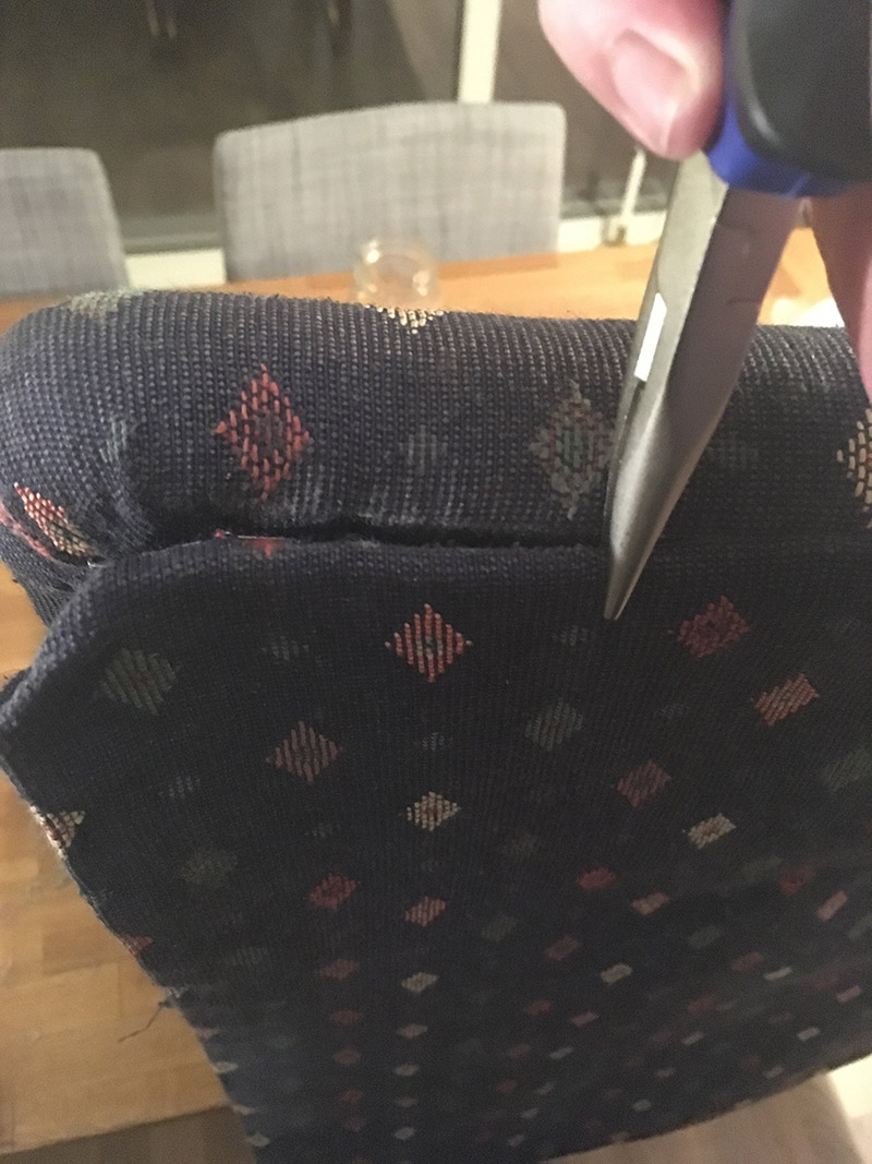
 After having removed the cardboard covering, the interior could finally be seen. As you can see from the picture above, the buttons on the back support are secured by string and pieces of electrical wire. Which made me wonder if someone had reupholstered this chair before, maybe.
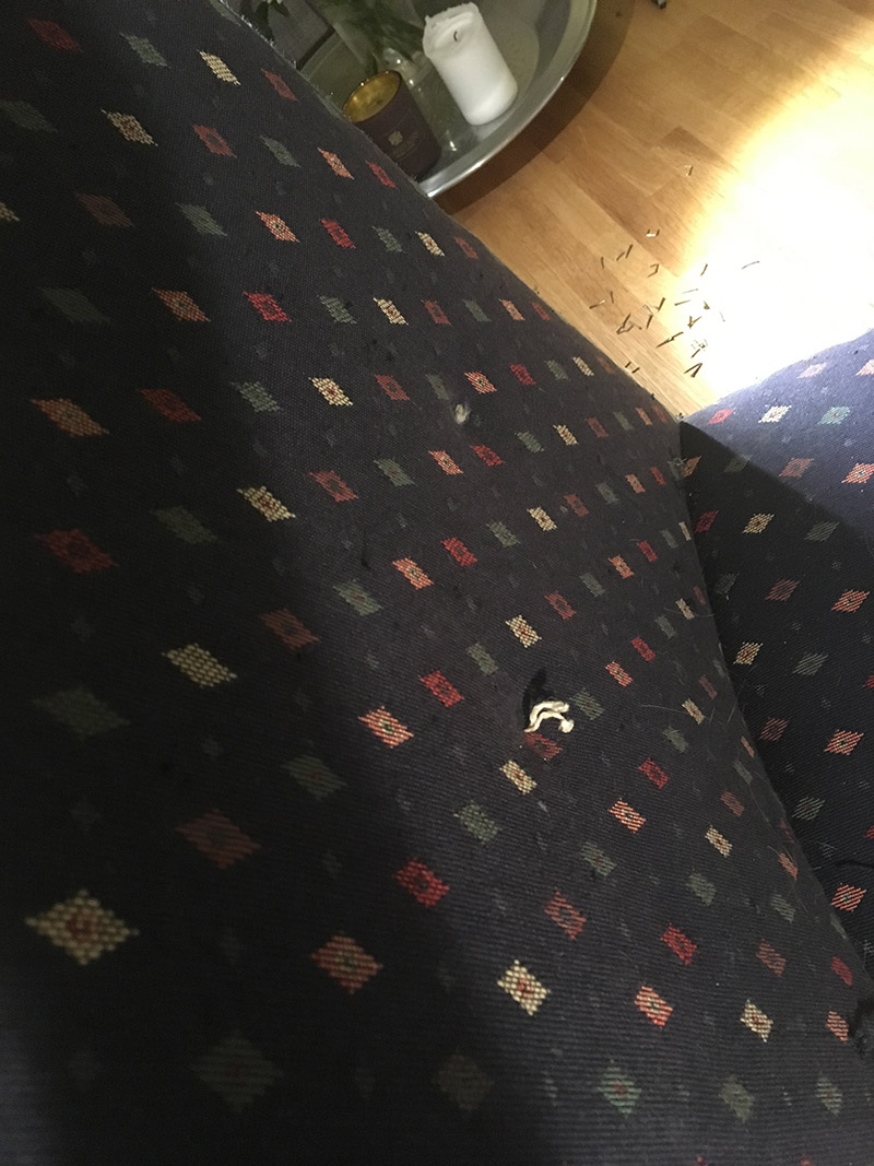
 Uh oh! Another layer of fabric, which meant even more staples to pull out. This was also the point where I realized I maybe needed a layer of cotton batting, underneath the yellow velour fabric. This helped me secure the foam cushions, and can give the surface a more even finish.
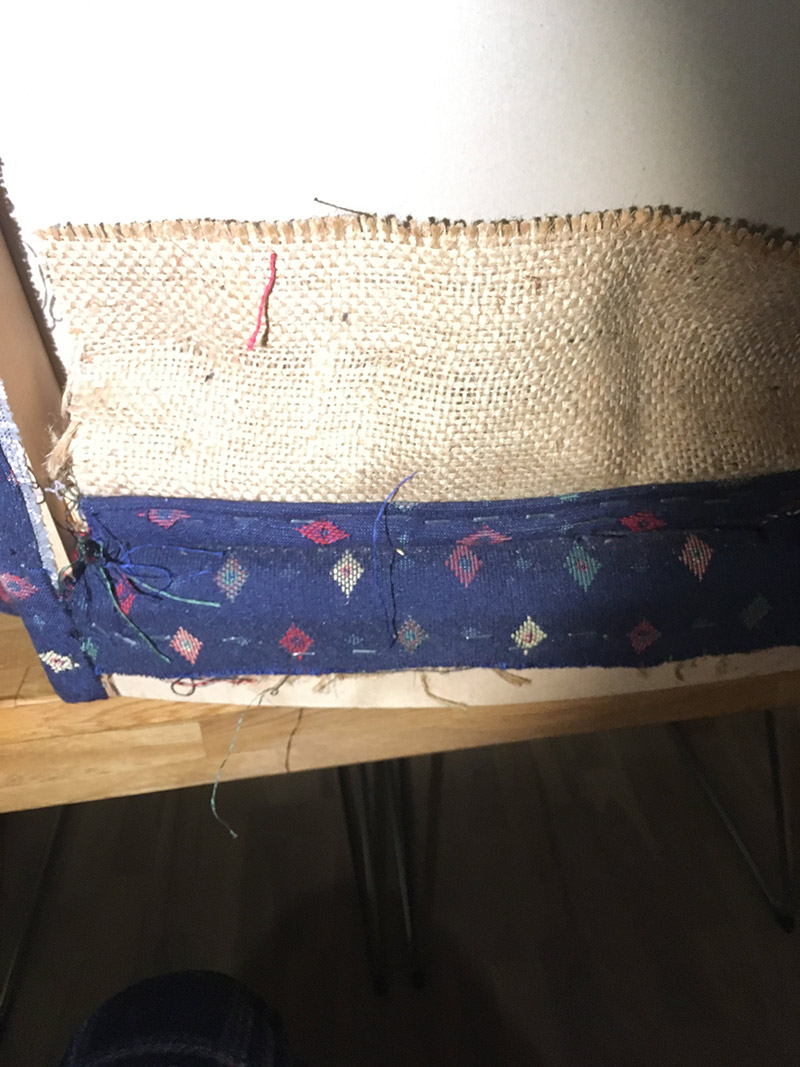 Shows how the fabric from the back support and chair pad is attached to the wood frame.
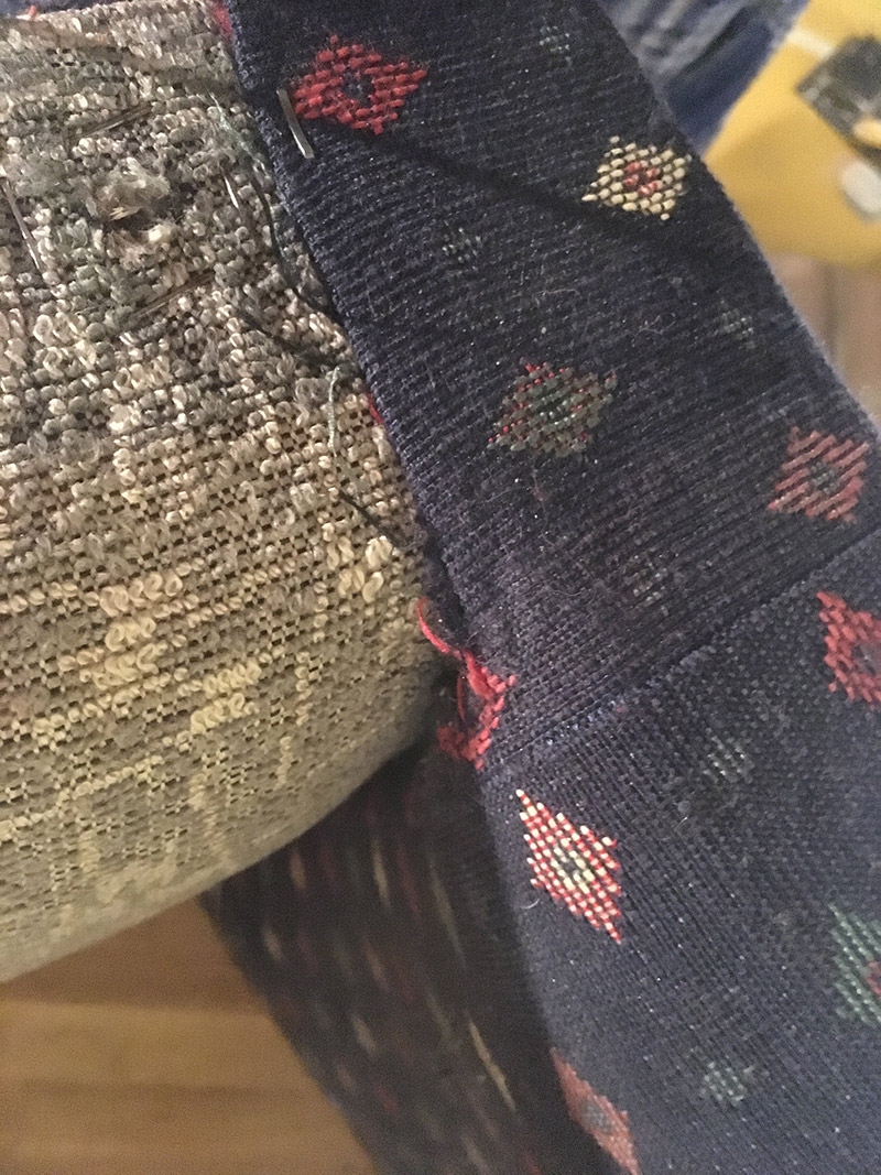
 that’s where all the missing domino pieces go! Found it inside the frame of the armchair.
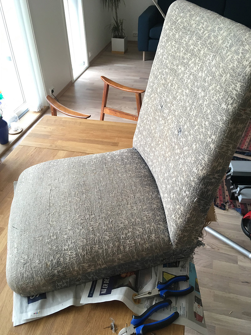 First layer removed. Another layer to go! My hands were getting sore at this point from pulling out so many staples.
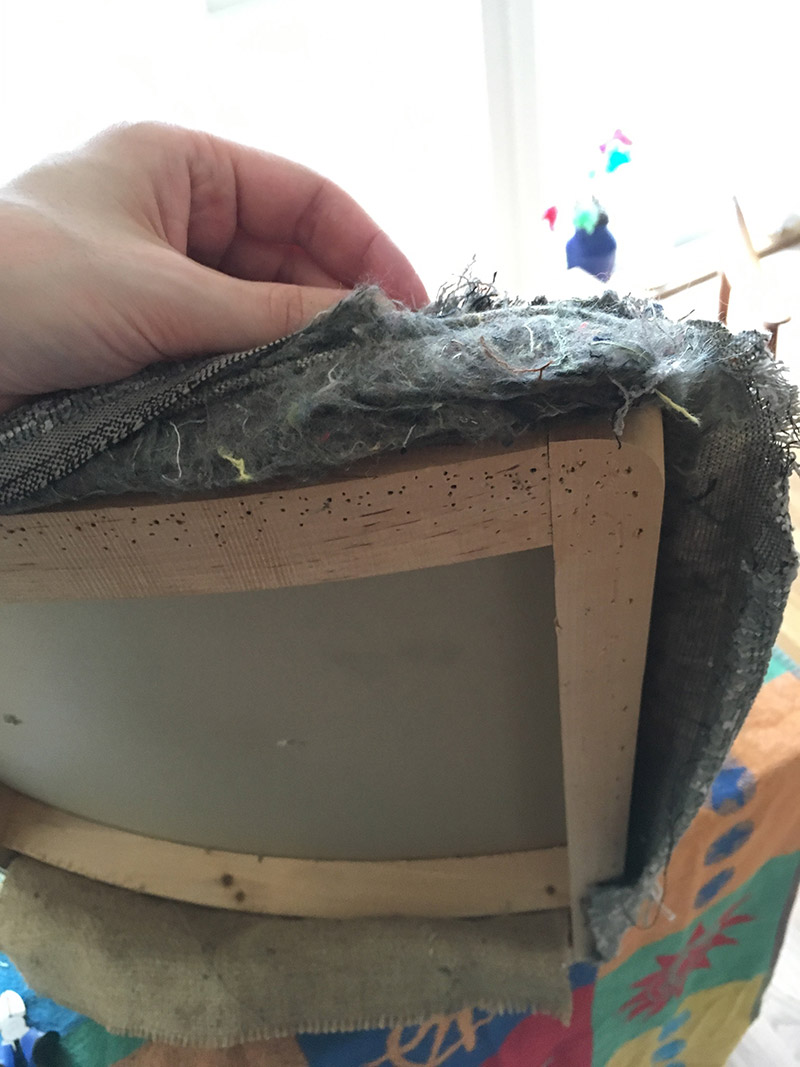 At this point I got my first glimpse of what furniture stuffing had been used. Something similar to needled wool felt.
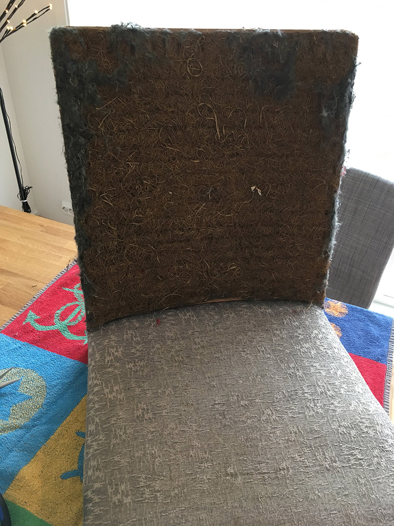 It was much more surprising to find hay beneath the needled wool felt. Apparently, it is common to use straw as a base layer in furniture filling. I had no idea!
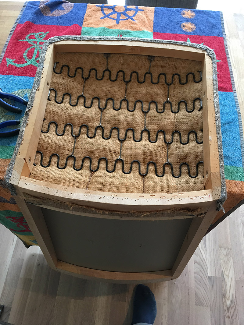
 Took a picture at this point to remember to staple around the hole where the bolts go. It seemed important.
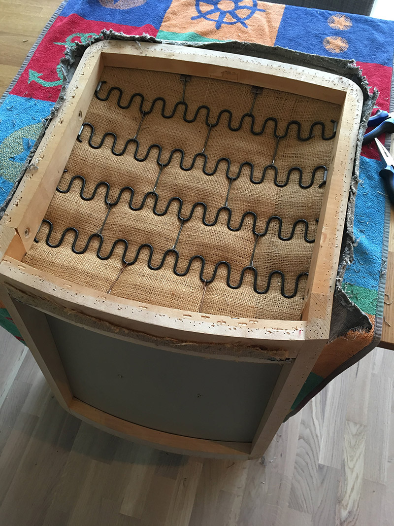
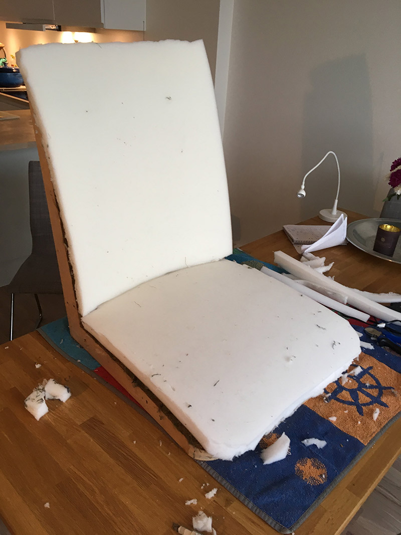 Here, I used the previous furniture filling to get an idea of how to cut the foam. I measured up the foam, drew lines with a sharpie, and did a rough cut of the foam. Afterwards, I put the foam on the chair and made some finer adjustments to it, as you can see in the picture above.
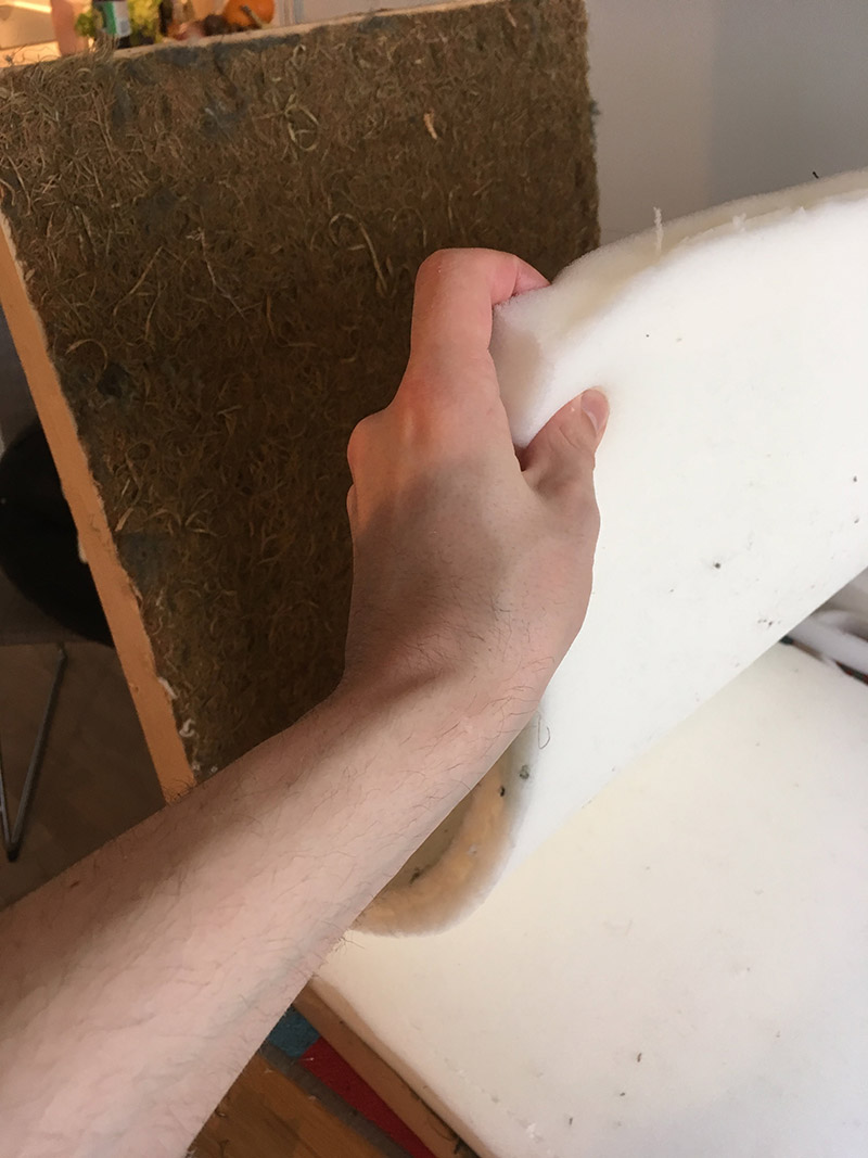
 After I was satified with the foam, I began working on the cotton batting.
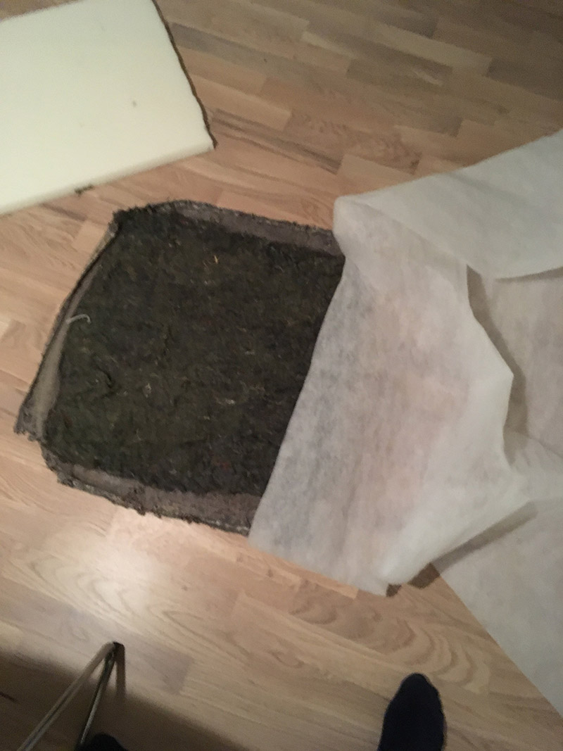 As you can see, I simply reused the old upholstery to get some rough measurements. I cut two large pieces of batting with scissors, that were more than enough to cover the back and pad. Any excess material I cut away after attaching it to the chair. It also helps having a large margin or seam allowance because the batting has a tendency to tear apart quite easily, and you want to pull very firmly on it when attaching it to the wood frame.
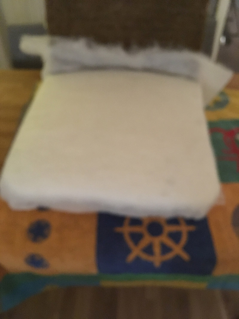
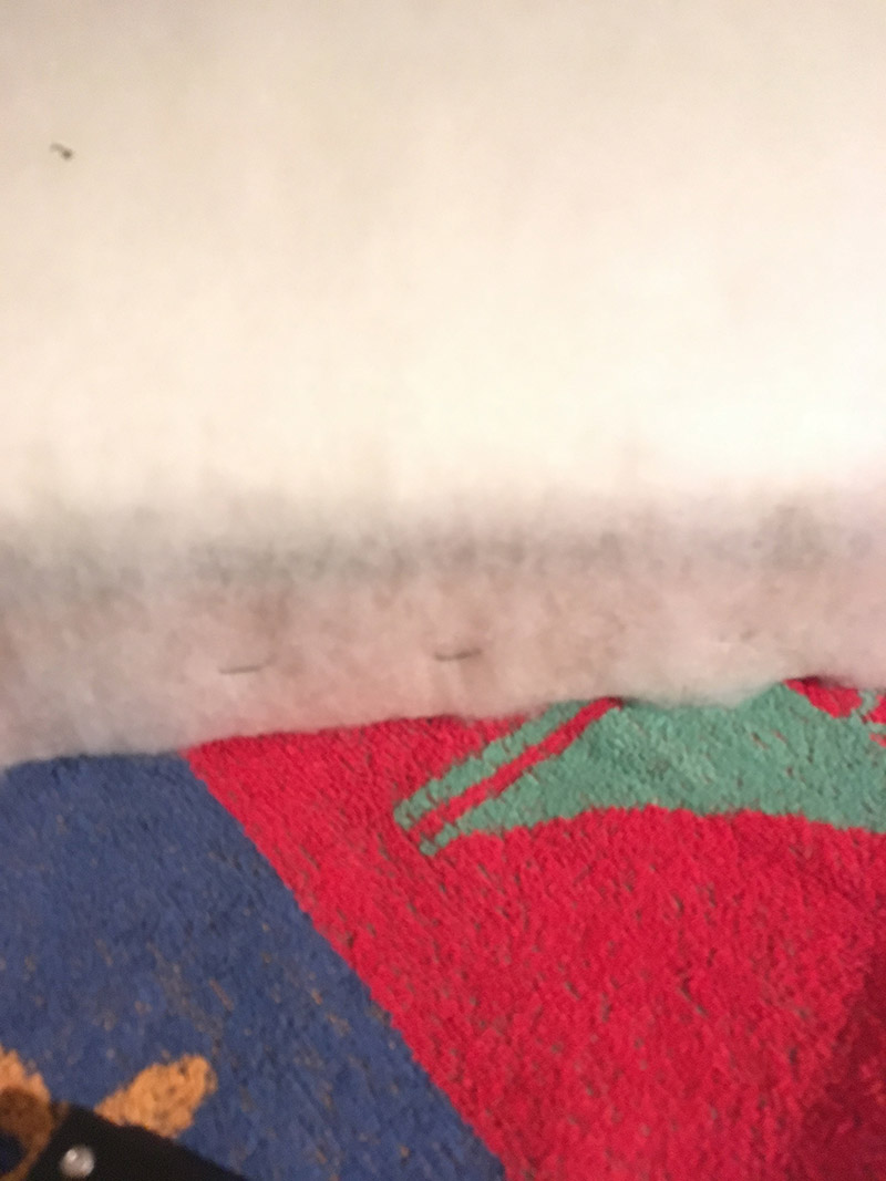 Having an extra person to pull the fabric does not hurt, here. At least until you can properly attach one side. I started stapling from the middle of one side, pulling, holding, and stapling. I continued this process towards each corner, but would stop around 10 cm from each corner. Then, I switch to the opposite site, doing exactly the same. From the middle, towards each corner. I repeated this for the final two sides, as well. Finally, I secured the corners in a similar manner, pulling and stapling.
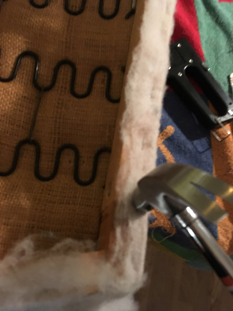 Some of the staples did not go all the way in. So, I used a hammer…
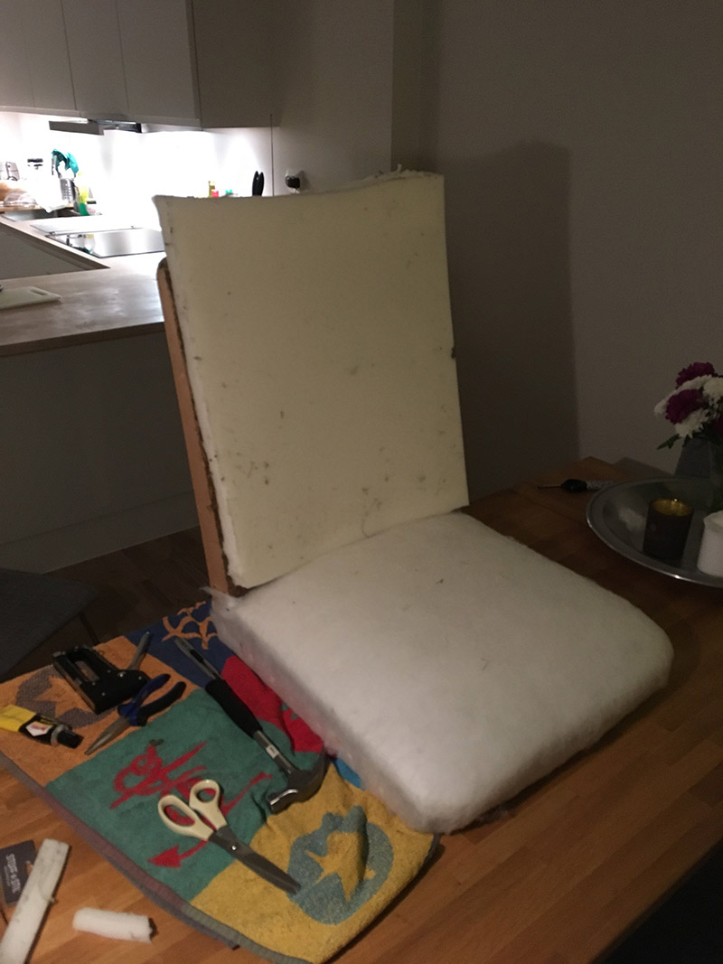
 The foam on the back support is extra long, since it wraps around the top edge of the wood frame.
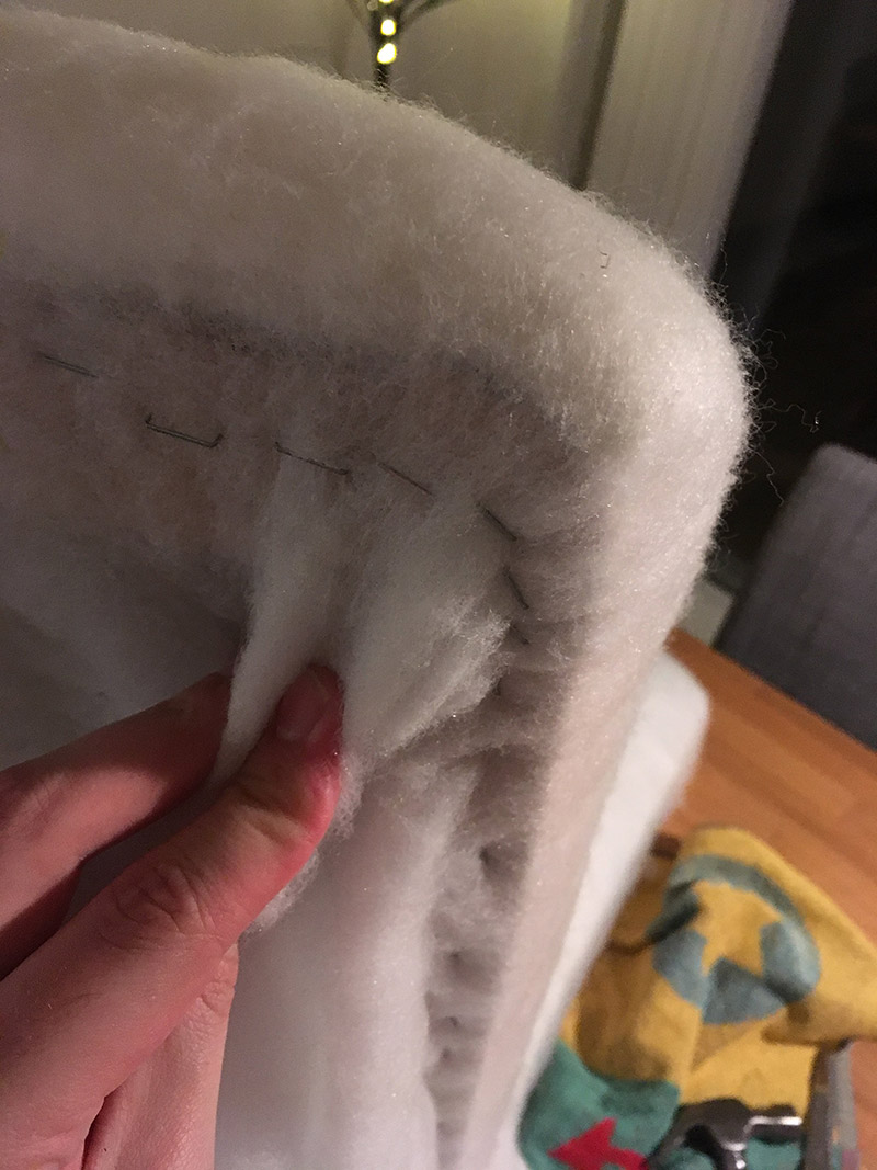 Again, I pull firmly on the batting before stapling, starting from the center of each side, and work myself towards the corners. In the picture above you see me kind of, trying to, demonstrate it on a completed corner.
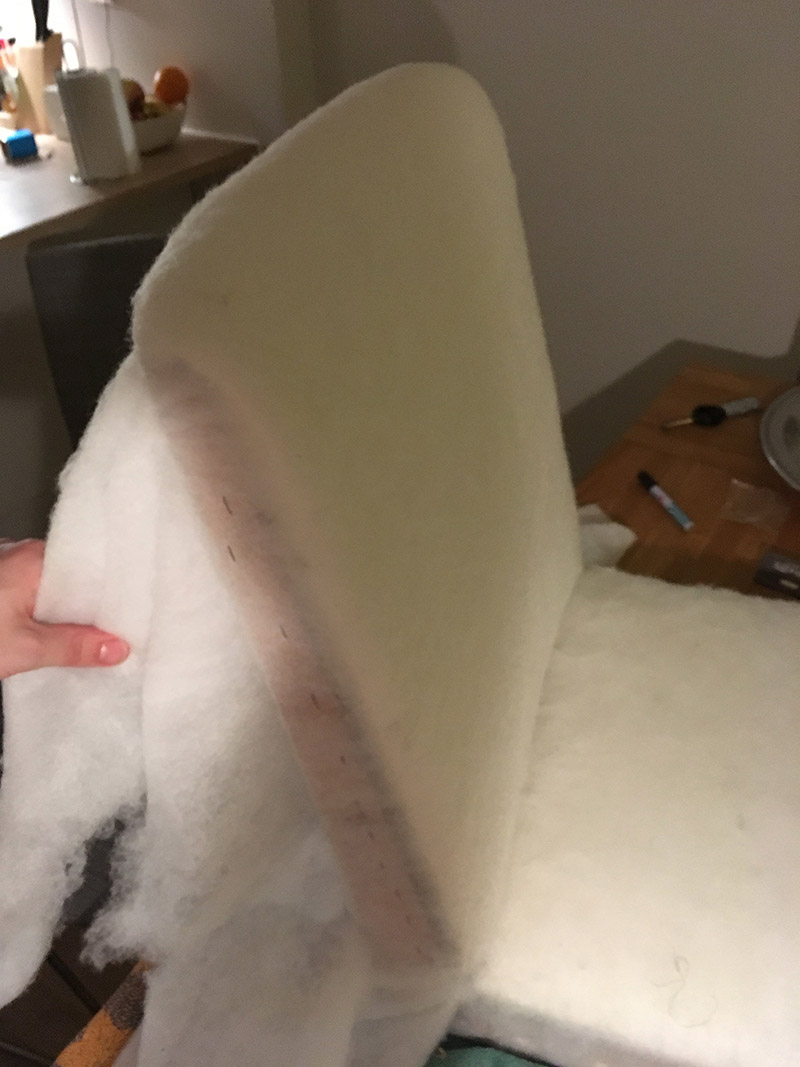
 As you can see, a lot of wasted cotton batting.
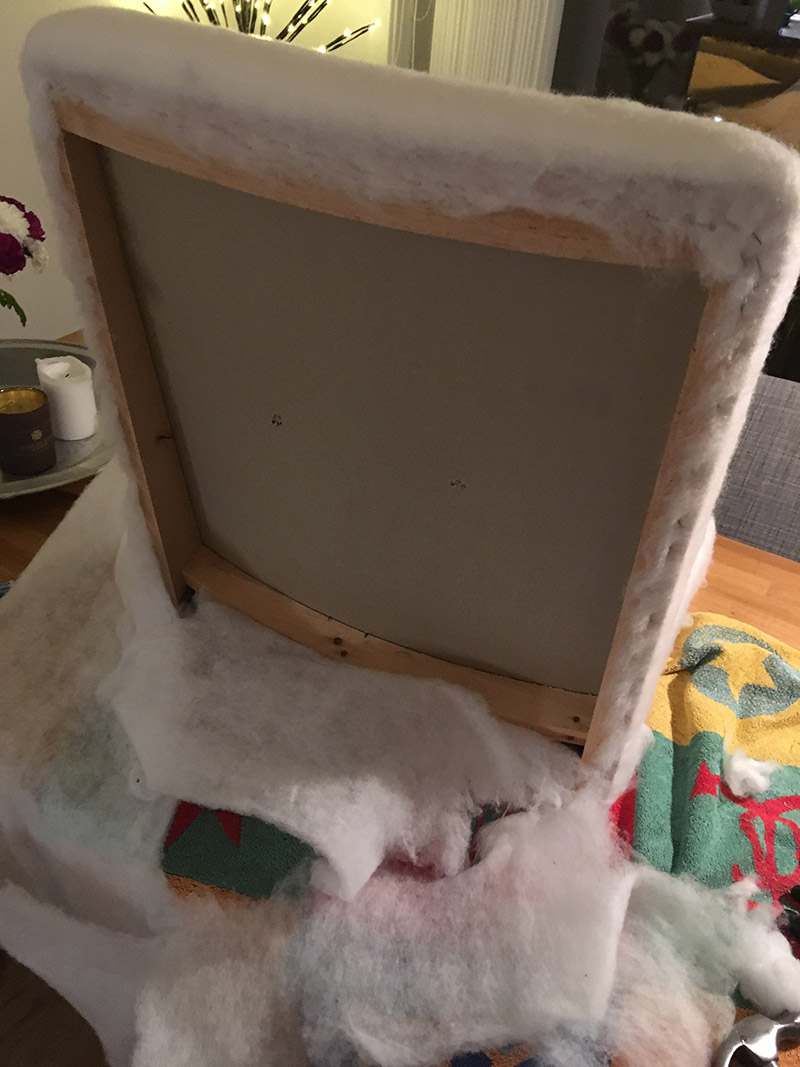 And finally, after having secured the batting to the wood frame, I simply cut away the excess.
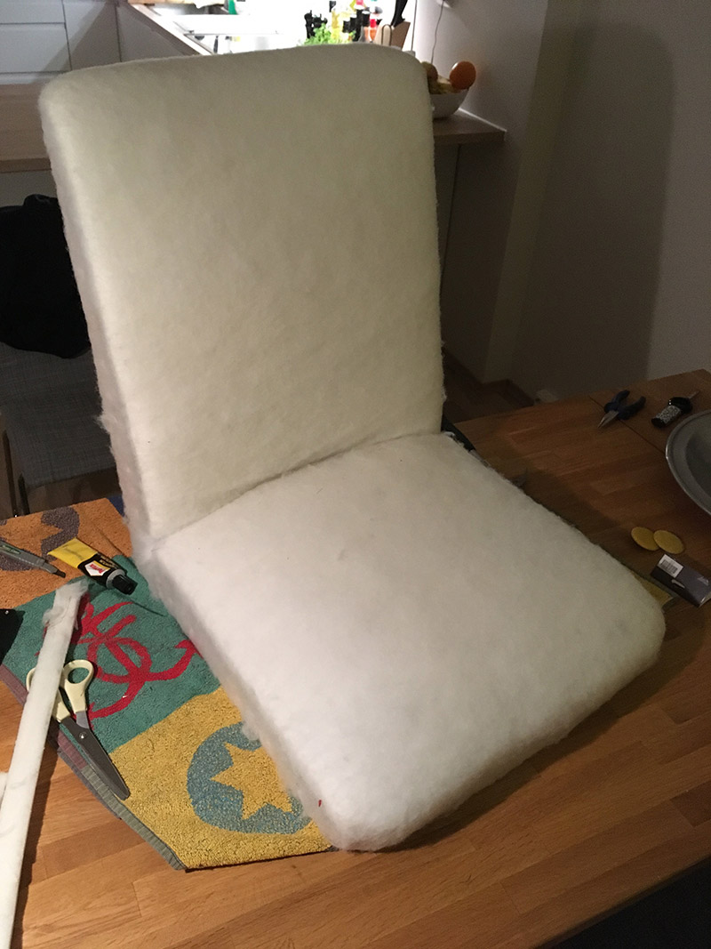
 There is not that much magic to it.
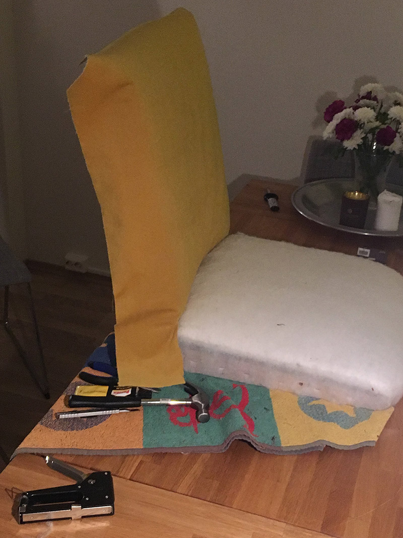 Testing the fit.
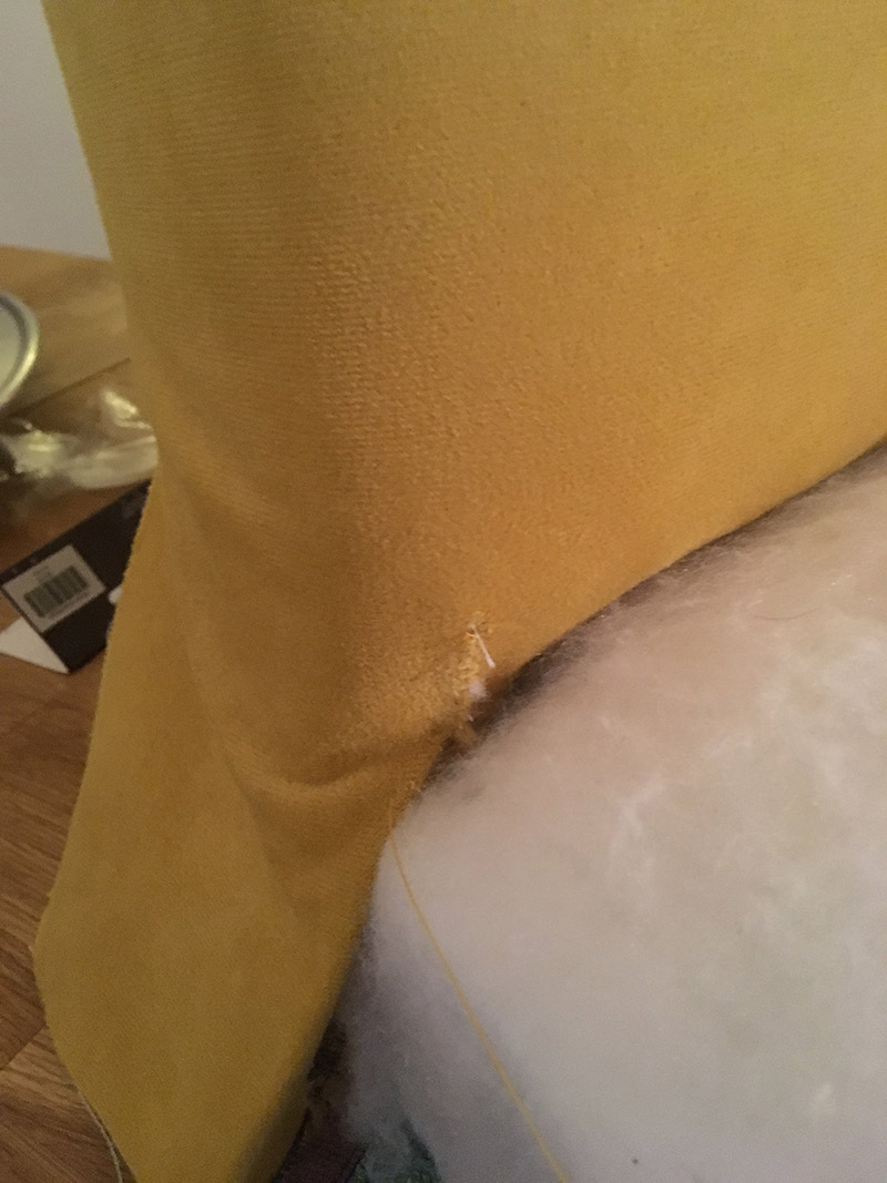 Or maybe there is a bit of magic to it. I managed to rip the fabric while attaching it to the frame, which meant I got to take the curved needle for a spin. The fabric had already been stapled to the wood frame, so it was a bit awkward sewing the rip.
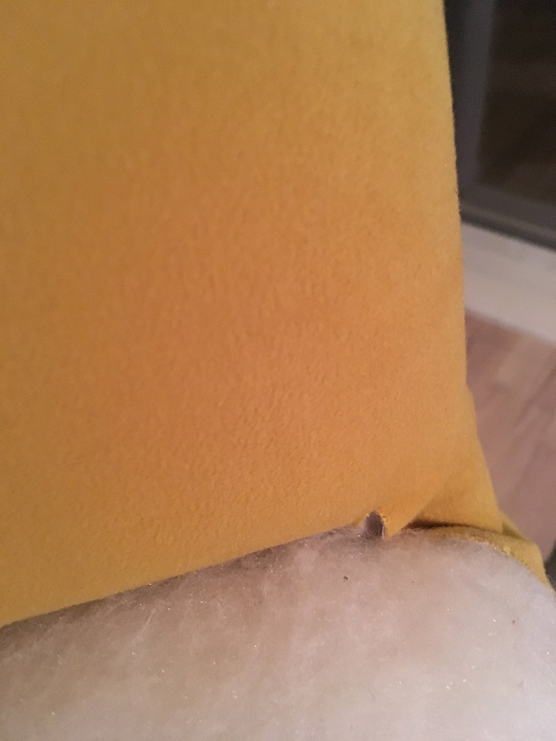
 The process here is exactly the same as for the cotton batting. From the middle, towards each side. Corners last. The only difference is that inaccuracies are now visible, so pull harder!
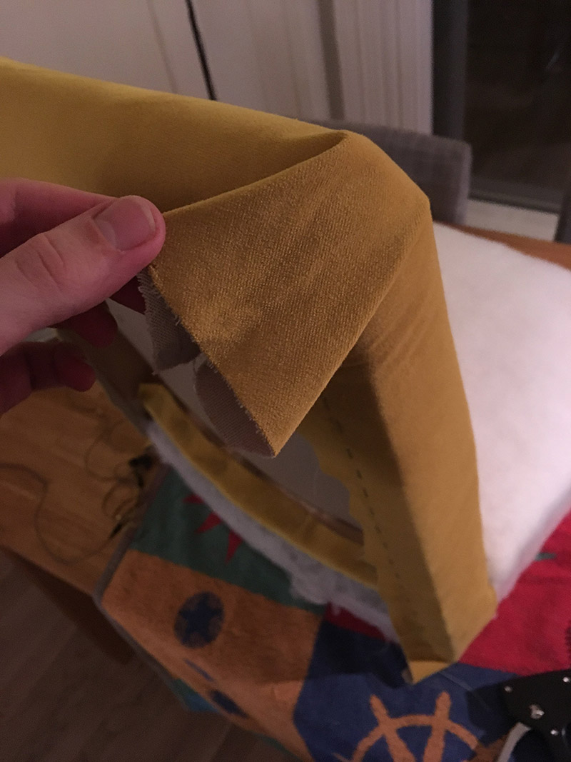
 As you can see in the pictures above, I tried to fold the corners in a consistent manner.
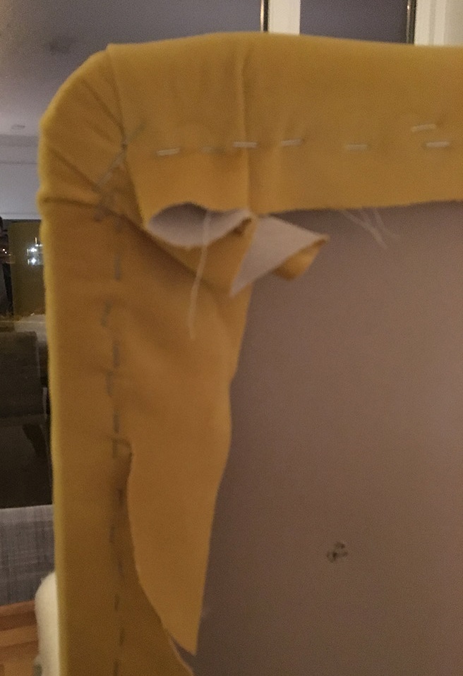 I did end up having to cut some excess fabric. Especially from the corners.
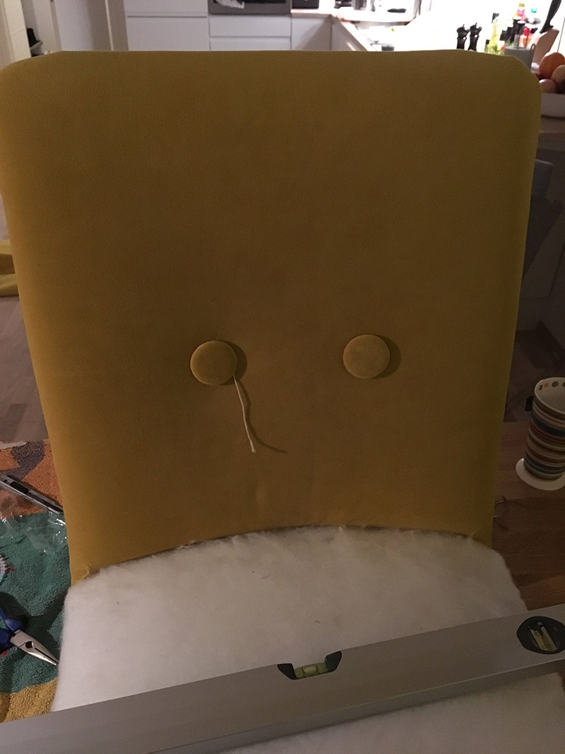
 I threaded some string on a needle, and poked holes in the fabric at around the same spots of the previous buttons. I did utilize a level and measuring tape to get the buttons on a pretty straight line.
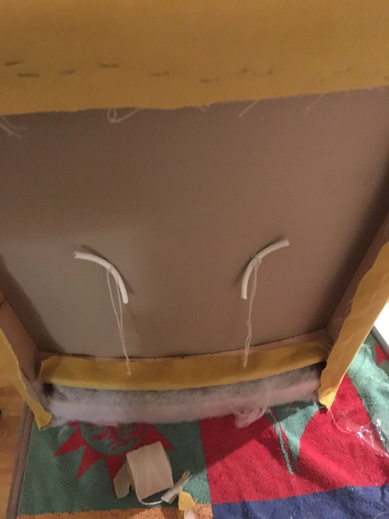 To use pieces of electrical wire to secure the buttons was actually a pretty smart idea. Had to copy that.
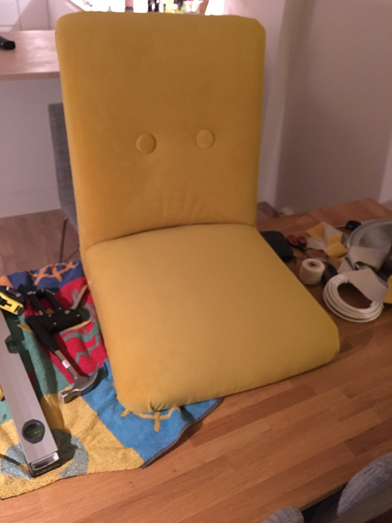 You can now start to see some flaws in the upholstery work. Either I did not pull hard enough when securing the bottom side of fabric on the chair support, or I might have put too little stuffing in. Not sure why. There are also some issues on the bottom front of the chair pad.
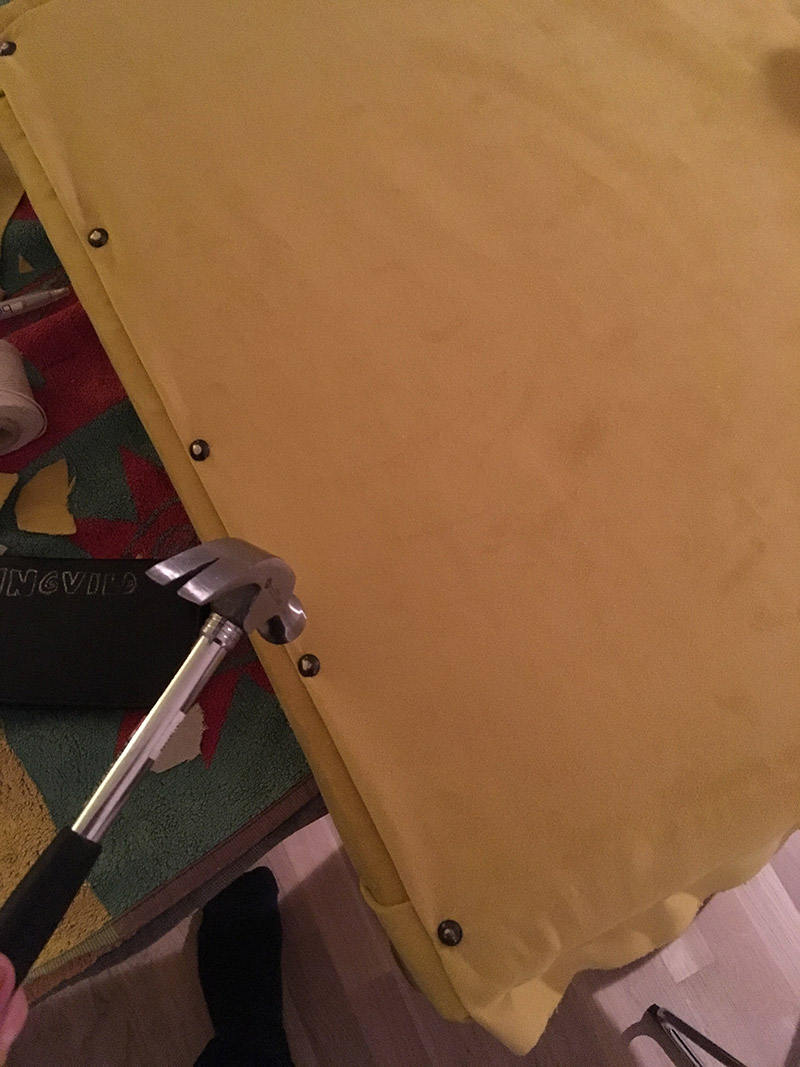
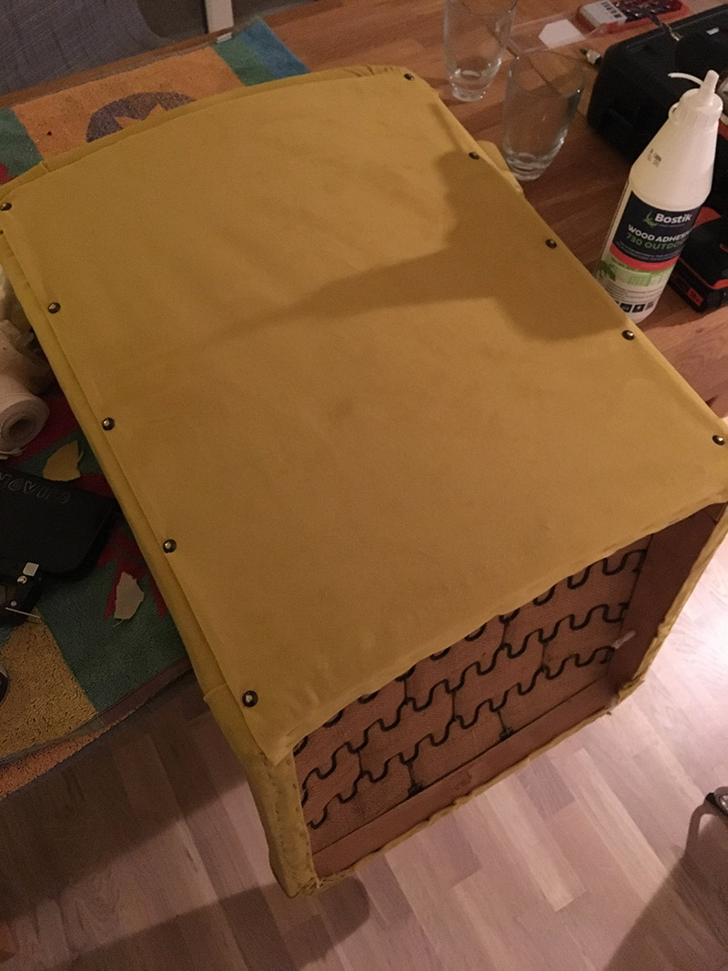 The next step, was to reattach the cardboard plate. As you hopefully can kind of see (sorry, for the lack of pictures!), is that the fabric is wrapped around the plate, except for at the bottom. the fabric and plate were secured to the chair frame by staples and upholstery nails.
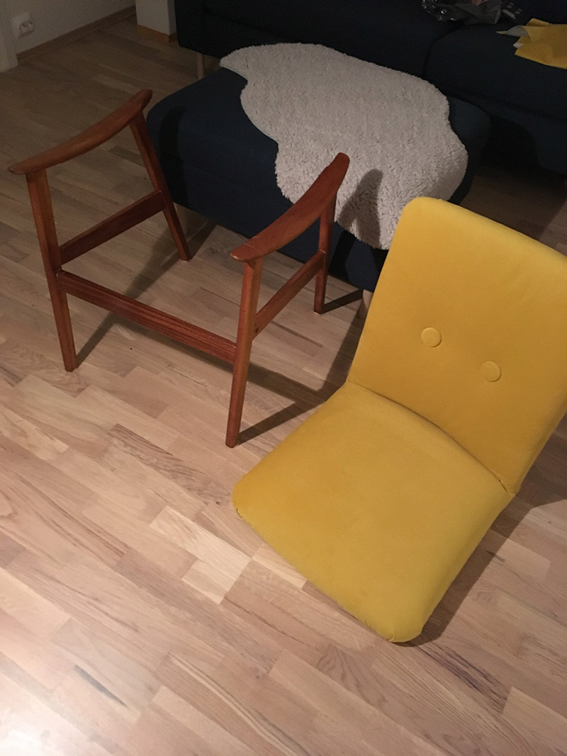
 Basically, I glued the base of the chair, and screwed the base and chair together in one go. I let the glue dry overnight.
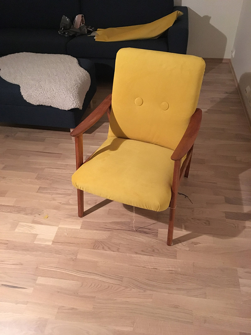
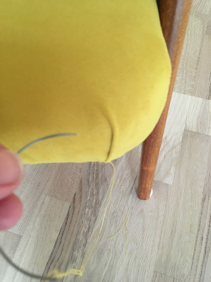 Each corner has two prominent folds, that almost create hidden pockets. As a final polish I sewed these shut with yellow denim thread.